Matrix Decomposition Algorithms for MIMO
receivers: Flexibility vs. Efficiency Tradeoffs in a
Library-based Tool-Assisted SDR Development
Venkates h Ramakrishnan
∗
, Tobias Veerkamp
∗
, Marc Adrat
†
, Gerd Ascheid
∗
and Markus Antweiler
†
∗
Institute for Integrated Signal Processing Systems, RWTH Aachen University, Templergraben 55, 52062 Aachen, Germany
†
Fraunhofer Institute for Communication, Information Processing & Ergonomics (FKIE), Wachtberg, Germany
Abstract—Multiple input and multiple output (MIMO) is one
of the key technologies used in wireless standards like LTE and
WiMaX. Matrix decomposition of the channel matrix in the form
of QR decomposition (QRD) is needed for advanced MIMO
demapping algorithms like sphere decoder. The implementation
of QRD has to be highly efficient due to its computation-
intensive nature. On the other hand, software defi ned radios
(SDRs) require flexibility in several forms, e.g. support for
different algorithms. The contradictory nature of flexibility and
efficiency requires tradeoffs to be made between them in SDR
development. In this paper, we analyze tradeoffs by using MMSE-
SQRD as a case study. We have implemented two algorithms for
performing SQRD in four different methods with varying d egree
of portability, efficiency and reusability. Focus will given on a
library based SDR development approach i n our investigations
where constraint aware mapping can be performed with tool
assistance at a high abstraction l evel.
I. INTRODUCTION
Multiple input and multiple output (MIMO) systems can
provide high throughput by exploiting multi-path propaga-
tion and diversity. It is one of the en a bling tech nologies in
upcoming wireless standards like LTE and WiMax. One of
the highly comp lex components in a MIMO system is the
MIMO demapper, which separates the superposed received
data stre ams into the multiple transmitted streams. In order
to simplify and perform MIMO demapping efficiently, several
matrix decomposition methods are used in conjunction w ith
MIMO detection schemes. Since matrix decomposition repre-
sents a computation intensive c ompon e nt of a MIMO receiver,
its implementation has a direct impact on the over-all system
efficiency and therefore has to be highly efficient. This makes
the implementation of matrix decomposition challen ging.
Flexibility, a key feature in software defined radios (SDRs),
is sought in several forms. For example, flexibility in choos-
ing algorithms and their implementation in a SDR hardware
platform can enable the radio to efficiently use, e.g. spectrum
resources, according to the different environmental conditions.
Portability, the ease with which an implementation of a wire-
less standard c a n be ported to different hardware platforms, is
another form of flexibility. Reusability is a common form for
This research project was performed in the Ultra High-Speed Mobile
Information and Communication (UMIC) research centre under the support of
the Technical Center for Information Technology and Electronics (WTD-81),
Germany.
enabling flexibility in SDR development. For example, if an
algorithm or implementation can be reused fo r performing a
different fun ctionality, it can (re)configured/programmed on-
the-fly.
Even though a flexible solution may not always yield the
same performance, e.g. with resp e ct to energy, when comp ared
to a dedicated solution, the difference can be made tolerable
with careful engineering and application specific optimiza-
tions. A key advantage of reusability is the reduction of the
system development time an d time-to-market. Portability can
be significantly increased with reusable components. However,
identifyin g such reu sable components and implementing them
in a flexible and efficient way can be c hallenging.
Efficiency, which is also a prerequisite for SDRs, can take
several form s. For example, en ergy efficiency is paramount for
increasing battery life in mobile devices. Area efficiency has
become important, particularly in hand-held devices, due to
the growing need to ac commodate more hardware elemen ts.
It is well known that fully flexible hardware architectures,
e.g. general purpose proce ssors (GPPs), are expensive in terms
of area and energy consumption. In order to improve energy
efficiency and at the same time meet the computation needs
of the application, heterogeneous hardware platfor ms are a
promising solution. Apart from the processing elements (PEs),
the type of implementation on a PE can play a vital role
on efficiency as well. For example, hand-coded assembly
implementation that is optimized for the ar chitecture of a
processor can consume less cycles, by a few orders of magni-
tude, when compa red to a generic C implementatio n. However,
implementation in C has high portability w hen compared to
assembly.
From the above discussions, it is clear that flexibility
and efficiency are contradictory in nature. Therefore, tr ade-
offs among them have to be made at every stage of SDR
development. However, in order to make the tradeoff decisions
it is important to quantify the differences in performance. This
requires implementation of an algorithm or a component on
a whole range of PEs, spanning G PPs, dedicated application
specific integrated circuits (ASICs), digital signal processors
(DSPs), field programmable gate arrays (FPGAs), etc. using
generic C, C with intrinsics and hand written assembly (fo r
programmable processors) and hardware description language
Proceedings of SDR'11-WInnComm-Europe, 22- 24 Jun 2011
Copyright(c) 2011 The Software Defined Radio Forum Inc. - All Rights Reserved39
(HDL) (for FPGA an d ASIC). Such a comprehensive investi-
gation is beyond the scope of this paper. One of the main
focus of our investigations is to analyze th e flexibility vs.
efficiency tradeoffs while implementing a wireless standard
using reusable algorithmic kernels.
Due to the offer of both portability and efficiency for SDR
development, th e library-based Nucleus methodology [1] is
used as the backbone for our investigations. The Nucleus
methodology is based on a standardized library, consisting
of algo rithmic computation intensive kernels, Nuclei. T he
description of a wireless standard is done using the Nuclei
library as the basis. Due to the standardization of the Nuclei
library, vendors can provide efficient implementation s for
Nuclei, known as Flavors, as a part of board support package
(BSP) for a hardware platform. Tools are used for selecting an
implementation from the BSP, that me ets the con stra ints of a
wireless standard like late ncy. This paper can also be seen as
a case study for identifying a Nucleus, which can be reused
in several standards for performing different functionalities.
The rest of the paper is structured as follows. The system
model that is used for our investigations is explained in
Section II. Our contributions and related work are given
in Section III. The algorithms that were implemented for
performing minimum mean squared error (MMSE) sorted
QR decomposition (SQRD) are explained in Section IV. The
different versions of implemen ting the MMSE-SQRD algo-
rithms and their building blocks are described in Section V.
Results and observations are presented in Section VI. Finally,
conclusions are drawn.
Notations: A matrix Q is denoted by a uppercase le tter,
jth column of Q is indicated by a lowercase letter q
j
. Q
j,k
indicates the matrix element at jth row and kth column. The
subscript in lowercase letter (which itself has a subscript of
upperc a se letter) of a matrix Q
n
T
×n
R
indicates th e dimension
n
T
× n
R
of Q (a square matrix has a single subscript). For
example, I
n
T
represents an identity matrix of order n
T
. A
matrix with a subscr ipt in lowercase letter a indica tes a
submatrix Q
a
of the augmented matrix
¯
Q. Re{Q
j,k
} and
Im{Q
j,k
} indicate the real and imaginary parts of Q
j,k
respectively. A complex and real nu mber is represented by the
symbol, C and R respectively. The superscript
H
indicates th e
Hermitian transpose. k.k denotes the Euclidean norm operator.
The superscripts ˆ and
T
indicate the estimated value and
transpose respectively.
II. SYSTEM MODEL
We consider a MIMO-OFDM system w ith n
T
transmitting
and n
R
receiving antennas. The received n
R
× 1 dimensional
signal vector y can be expressed as
y = Hs + n (1)
where H is the n
R
× n
T
channel matrix, s is the n
T
× 1
transmitted signal vector an d n is the n
R
× 1 noise vector
with zero mea n and variance
1
2
σ
2
n
respectively.
MMSE solution, which takes the noise in the system into
account for estimating the transmitted signal vector at the
receiver side, offers better bit error rate (BER) performance
when compared to zer o forcing (ZF) solution (see Figure 1).
Therefore, this pap e r considers a MMSE solution for imple-
mentation. The channel matrix H has to be extended to the so
called complex-valued augmented channel matrix
¯
H, which is
defined as
¯
H =
"
H
q
n
T
E
s
σ
n
I
n
T
#
(2)
where E
s
is the transmitted signal power. I
n
T
denotes a
n
T
× n
T
-dimensional identity matrix. The inverse of the
complex augmented chann e l matr ix leads to the estimation
of the transmitted symbol vector
ˆ
s.
ˆ
s =
¯
H
−1
y
0
n
T
(3)
0 5 10 15 20 25 30
10
−6
10
−5
10
−4
10
−3
10
−2
10
−1
10
0
SNR (dB)
Uncoded BER
ZF−QRD, SIC
ZF−OTSQRD, SIC
ZF−SQRD, SIC
MMSE−OTSQRD, SIC
MMSE−SQRD, SIC
MMSE−SQRD, Sphere Decoder
Fig. 1. Uncoded BER performance of a 4 × 4 MIMO system using 16QAM
modulation for different MIMO preprocessing schemes
A. MIMO Processing
One of the most processing inten sive blo cks in the MIMO
receiver is MI MO processing (also mentioned as MIM O
demapp ing), wh ic h reverses the channel effects in ord e r to
recover the transmitted stream from the re ceived superposed
data streams. Figure 2 illustrates the block diagr am of M IMO
processing. Th e functionality of MIMO processing can be
separated into MIM O preprocessing and MIMO detection. The
functionality of the preprocessing block depends on the MIMO
detection scheme. MIMO detection schemes can vary from
the simple linear detection m e thod to th e advanced methods
like sphe re decoder (SD). Figure 1 illustrates the difference in
BER performa nce between successive interference cancelation
(SIC) and depth first, sphere decoding scheme.
40

Channel
Estimation
Noise
Estimation
MIMO Processing
MIMO
Preprocessing
(QRD)
MIMO
Detection
(SIC)
Estimated
Signal
Vector
Fig. 2. Block diagram of the MIMO processing based on QRD
B. MIMO Preprocessing
For perform ing MIMO detection using the linear technique,
the preprocessor can compute th e matrix inversion of H. Since
advanced MIMO detec tion schemes like SIC and tree-based
SD need the QR dec omposition (QRD) of the channel matrix
H, the preprocessor co mputes QRD while using them .
Implementation of preprocessing block can be critical for
wireless standards tha t support very h igh thro ughput and
therefore should be highly efficient. To illustrate this point,
let us consider two scen a rios in LTE standard. Assuming a
maximum spe e d of the mobile h andset as 350 km/hour and
a carrier frequency o f 2.5 GHz, the coherence time is given
by 1.2 milli-second (ms) [2]. With 1200 data carrying sub-
carriers, time to perform the QRD of H belonging to each
sub-carrier is: 1.2 ms / 1200 = 1 micro-second (µs). For a
slightly relaxed scenario with the speed of mobile handset as
45 km/hour (coherence time of 10 ms) and other conditions
being the sam e as above, the ma ximum time to perform QRD
is: 8.3 µs. In order to meet such low timing, implementatio n
of MIMO preprocessing must be highly efficien t making it
challengin g.
As shown in Figure 1, sorting the channel matrix before
performing QRD improves BER performance significantly,
resulting in the so-called SQRD. We have considered only
SQRD algorithms in this paper. As 2 × 2 MIMO is of
reasonable complexity and is proposed for LTE to achieve
a peak downlink download ra te of 150 Mbps, we have not
considered higher order MIMO systems for impleme ntation
in this paper. More over, most of th e observations made from
our results are general in na ture and a pplicable to higher
order MIMO systems as well. It is important to note that
one-time full-column sorted QRD (OTSQRD) technique in a
4 × 4 MIM O system becomes fully sorted technique, referred
as SQRD, in a 2 × 2 MIMO system.
III. CONTRIBUTIONS AND RELATED W ORK
In this paper, we have implemented two algorithms, mod-
ified Gram Schmidt (MGS) and Givens r otation (GR) f or
performing MMSE-SQRD. The GR algorithm is implemented
in several ways that are based on algorithms and components
which are highly reusable. For example, the coordinate rotation
digital computer (CORDIC) algor ithm, which has been used
for impleme nting GR, can be used for realizing several other
functionalities like phase cor rection [3]. Due to the nature of
implementation (without flexibility), MGS can be used as a
dedicated solution in this paper and can be used for comparing
the performance of the flexible implementations of GR. The
Texas Instruments C64x+ DSP is used as the PE for our
analysis. For analy z ing the porta bility vs. efficiency trad e-
offs, all the implementation -variants (men tioned as variants
in th is paper) have been realized in floating-point C, fixed-
point C, fixed-poin t C with intrinsics and hand-optimized
Very Long Instruction Wo rd (VLIW) a ssembly. This includes
both 16-Bit and 32-Bit implementations for analyzing different
input/output (I/O) data-width. Due to the h igh computation al
complexity in performing QRD, it serves as a good case study
for our analyses o n flexibility vs. efficiency tradeoffs.
Several meth ods such as GS-, LDL-, LR-, LU-, QR- and
Jacobi singular value decomposition (SVD) can be used for
performing matrix decomposition. Among the m, QRD is a
popular candidate for MIMO preprocessing. This is due to
the necessity for QRD of th e ch a nnel matrix in some ad-
vanced MIMO detection schemes like SD. Three most p opular
algorithm s for implementing a QRD are: the Householder
reflections algorithm [4, 5], the MGS algorithm [6, 7] and the
GR algorithm [8, 9]. As we are considering o nly the MGS and
GR algor ithms, our focus is re stricte d to only these alg orithms.
Numerous ASIC solutions have bee n published for im-
plementing QRD [10–13]. Authors in [11, 14] describe a
MIMO processing VLSI architecture on GR based QRD.
Both a rchitectures use the CORDIC algorithm. The tradeoffs
between finite word length precision, which is determine d
by the number of CORDIC iterations, and latency ha s been
investigated in [11]. Similarly, VLSI architectures ba sed on
MGS for QRD are presented in [6, 15, 16].
Several decomposition methods have been implemente d on
FPGAs as well [17–2 0]. The perform ance differences between
the QRD algorithms, due to the d ifferences in the fixed-
point implementations, can be clearly seen in the mentioned
publications.
QRD implementations on both floating- and fixed-point
DSPs exist. The authors in [21] have analyzed the performance
differences of numerical a lgebra algorithms between imple-
mentation in a fixed-point DSP, using TI C64x+ and a floating-
point DSP, using TI C67x+. Several matr ix decomposition
methods like SVD, Cholesky, LU, QRD and Gauss-Jordan
have been implemented on a floating-point TI 6713 DSP and
analyzed with respect of computational complexity, latency
and memory requirements in [22].
Most of the above work s have predominantly focused on
developing efficient implementations of matrix decomposition
algorithm s for MIMO receivers. Tho ugh algorithms have been
implemented after making complexity and numerical stability
compariso ns, the analysis on flexibility vs. efficiency tradeoffs
which is e ssential for SDR development is missing. Further-
more, reusability and portability investigations are missing as
well. This paper tries to fill these gaps by analyzing and
implementing the MGS a nd GR algorithms for performing
MMSE-SQRD. In order to a utomate SDR development, we
lay focus on the aspects that are imp ortant for tool assistance
throughout our investigations.
41

IV. ALGORITHMS
The M MSE-SQRD of a complex augmented channel matrix
¯
H using the MGS [23] and sequenc e of GRs is presented
in this section along with the com putational complexity for
a 2 × 2 MIMO system. The modifications for perf orming a
one-time full column sorting b e fore executing QRD which is
equivalent to a full iterative sorting for a 2 × 2 MIMO system
are highlighted.
A. MMSE-SQRD based on modified Gram-Schmidt
The MMSE-SQRD operation based on the MGS algorithm
is listed in Algo rithm 1. The augmented complex-valued
channel matrix
¯
H is assigne d to
¯
Q matrix, R is initialized
with a zero matrix, 0
n
T
and th e permutation matrix P with
I
n
T
. First, the colu mn norm vector α o f ea ch column in
¯
Q
is calculated (lines 1 to 3). Next, a full column sorting is
performed. The column ¯q
i
with the smallest squared l
2
-norm
is processed first. Finally, the actual QRD is done as shown
from lines 7 to 14 in Algorithm 1.
The diagonal element R
j,j
is calculated as shown in line 8
and is used for dividing the column ¯q
j
(line 9). The upper
diagona l elements in row j of R are computed according
to R
j,k
= ¯q
H
j
¯q
k
, where k = j + 1, j + 2, ..., n
T
. In each
sub-iteration, column q
k
is updated according to line 12 in
Algorithm 1. The MGS algorithm executes the QRD in n
T
steps, with the result as shown in Equation 4.
¯
H =
¯
QRP
T
=
Q
a
Q
b
RP
T
(4)
Input:
¯
Q =
¯
H, R = 0
n
T
×n
T
, P = I
n
T
1: for i = 1, 2, ...n
T
2: α
i
= k¯q
i
k
2
3: end
4: for i = 1, 2, ...n
T
5: sort columns in
¯
Q and P, correspon ding to norm α
6: end
7: for j = 1, 2, ...n
T
8: R
j,j
=
q
¯q
H
j
¯q
j
9: ¯q
j
=
1
R
j,j
· ¯q
j
10: for k = j + 1, j + 2, ..., n
T
11: R
j,k
= ¯q
H
j
¯q
k
12: ¯q
k
= ¯q
k
− R
j,k
¯q
j
13: end
14: end
Output: Q
aj,i
=
¯
Q
j,i
with j = 1, 2, ...n
T
, i = 1, 2, ...n
R
Alg. 1: MMSE One -Time-Sorted QRD based on MGS
The MGS algorithm is mainly based on multiplication
(C ×C and C×R), inverse and square root operations. Table I
illustrates the count of basic operations in pe rformin g one
MMSE-SQRD operation using MGS algorithm for a 2 × 2
MIMO system.
Operation Count
SQRT 2
INV 2
C × C 9
R × C 5
TABLE I
OP ERATION COUNT FOR PERF ORMING MMSE-SQRD USING MGS
ALGORI THM I N A 2 × 2 MIMO SYSTEM
B. MMSE-SQRD based on Givens rotations
The MMSE-SQRD operation performed using a series of
GR is listed in Algorithm 2. Initialization of Z is d one
accordin g to Equation 5. Z is a compound matrix o f the
augmen te d complex-valued channel matrix
¯
H, an n
T
× n
T
-
dimensional identity matrix and a zero matrix in the lower
right section of matrix Z. The righ t side of the Z matrix is used
for concate nation of the GRs to form the unitary
¯
Q matrix.
The GR a lgorithm upper triangularizes the left half of matrix
Z. Permutation matrix P keep s track of the sorting .
Z
(0)
=
"
H I
n
T
q
n
T
E
s
σ
n
I
n
T
0
#
(5)
where Z has the dimension of (n
R
+ n
T
)× (n
T
+ n
R
). The
outcome of the GR algorithm after the last iteration N is
Z
(N)
=
R Q
H
a
0 Q
H
b
(6)
The column norm vector α of
¯
H is calculated in lines
1 to 3 of Algorithm 2. A full column sorting is executed
between lines 4 and 6. The procedure for QRD is illustrated
from line 7 to 10. The MMSE-SQRD operation using GR
algorithm computes the
¯
Q and R matrices in n
T
steps. In
each step, a series of GR is computed and multiplied with Z
to eliminate the j +n
R
, i+n
R
−1, ..., i+1 rows of z
i
. In other
words, e ach rotation zeros an element in the subdiagonal of
the given matrix, forming an upper-triangular R matrix. The
concatenation of all applied GR forms the unitary matrix
¯
Q. In
each step, the rotation is only executed on two specific rows.
The complex-valued matrix processing using GR is an
extension of the re al-valued matrix p rocessing and can be
separated into two operations: C → R and R → 0. C → R
operation tra nsforms a complex matrix entry Z
p,k
from the
complex pla ne into the real plane. The rotation matrix θ
C
of
C → R o peration is given by
θ
C
(p, φ) =
1 0
0 e
−iφ
p
(7)
p
with rotation ang le
φ(p, k, Z) = − arctan
Im{Z
p,k
}
Re{Z
p,k
}
(8)
θ
C
(p, φ) is a 2-dime nsional identity matrix with e
−iφ
at
42

Input: Z = Z
(0)
, P = I
n
T
1: for i = 1, 2, ...n
T
2: α
i
= k
¯
h
i
k
2
3: end
4: for i = 1, 2, ..., n
T
5: sort the first n
T
columns in the first n
R
rows of Z
(0)
and P, corresponding to α
6: end
7: for j = 1, 2, ..., n
T
8: perform a series of G Rs, θ
u
such that rows j +
1, ..., n
R
+ n
T
of column z
j
become zero
9: Z = (
Q
in
R
u=(j−1)n
R
+1
θ
u
)Z
10: end
Output:
R
j,i
= Z
j,i
with i, j = 1, 2, ..., n
T
Q
H
a
j,i
= Z
j,i+n
T
with j = 1, 2, ..., n
T
, i = 1, 2, ..., n
R
Alg. 2: MMSE One-Time-Sorte d QRD based on GR
position p, p. The elimination of real valued matrix elements
is performed by R → 0 operation. The rotation matrix for
R → 0 operation is given by
θ
R
(q, p, φ) =
cos(φ) sin(φ)
− sin(φ) cos(φ)
q
p
(9)
q p
with rotatio n angle
φ(q , p, k, Z) = − ar c tan
Re{Z
q,k
}
Re{Z
p,k
}
(10)
Both C → R and R → 0 operations can be further
separated into b asic vecto ring and rotation o perations. The
vectoring operation rotates a complex value into the real
plane and provides the rotatio n angle. In other words, the
vectoring operation performs the computation of the rotation
angle (shown in Equation 8). Furthe rmore, it obtains the angle
needed for rotating the real valued matrix elements (shown in
Equation 10).
The rotation operation rotates one complex value into an-
other b y a specific an gle. It is importan t to note that the
rotation operation has to be performed, using the rotation
matrices 7 and 9, on the other en tries in the rows of Z which
are affected by C → R and R → 0 opera tions. Table I I lists
the required number of these basic operation s for performing
MMSE-SQRD on a 2 × 2 MIMO system. Note that the GR
algorithm can be easily parallelized, however, it needs a higher
number of opera tions when co mpared to MGS algorithm for
performing MMSE-SQRD.
V. IMPLEMENTATIONS
The building blocks, which have been reused for different
variants of implementation, are first presented in this section
followed by the variants themselves.
Basic Operation Count
Vectoring Rotation
C → R 4 7
R → 0 4 16
TABLE II
NUMBER OF BASIC OPERATI ONS FOR PERFORMI NG MMSE-SQRD USING
GR ALGORITHM IN A 2 × 2 MIMO SYSTEM
A. Building Blocks
1) TI IQMath Library: In order to increase the implemen-
tation efficiency and decre ase the time-to-market, TI provides
IQmath library [24] with impleme ntations of well-known
mathematical functions for the C64x+ DSP. This library is
a collection of m athematical 32-Bit fixed-point functions.
Table III lists the functions fr om the IQmath library that are
used in ou r MMSE-SQRD im plementations.
Algorithm Name Processing time
in cycles
MGS
IQNsqrt 79
IQNdiv 73
GR
IQNsin 56
IQNcos 54
IQNatan2 118
TABLE III
LIS T OF USED F UNCTIONS FROM THE IQMATH LIBRARY
The same functions were used for both 16-Bit and 32-Bit
implementations, except inverse and square root functions.
Hand written optimized implem entations of these two func-
tions, w hich gave a better perform ance when compared to
the 32- Bit I Qmath librar y f unctions, were used for 16-Bit
implementation.
2) CORDIC: The CORDIC algorithm is versatile algorithm
widely used in digital signal processing applications. Typically,
it is used for performing a vector pseudo-rotation of a given
two-dimensional vector in a sequenc e of micro iterations with
discrete step size. One advantage of the CORDIC algorithm
is that it can be imp lemented by employing, predominantly,
shift and add ope rations.
CORDIC
Kernel
CORDIC
Vectoring
Preprocessing
CORDIC
Vectoring
Postprocessing
Fig. 3. Implementation of CORDIC vectoring
Figures 3 and 4 show the implementation of vectoring and
rotation operations usin g CORDIC. n denotes the number of
applied CORDIC iterations and k represents the scaling factor
with which the fin al result is multiplied. The rotation angle is
marked a s φ.
Note that the CORDIC imp lementation in the rotation mode
can be modified for computing sine and cosine values of a
43

CORDIC
Kernel
CORDIC
Rotation
Preprocessing
CORDIC
Rotation
Postprocessing
Fig. 4. Implementation of CORDIC rotation
given rotation angle φ, it is denoted as sincos implemen tation
in this paper.
B. Variants of Implementation
The different variants f or implementing the algorithms are
presented in this section. Highly portable imp le mentations are
done in floating-p oint and fixed-po int usin g generic C. Both
16-Bit and 32-Bit versions have been implemented in the
fixed-point format. Highly optimized VLIW code has been
hand-written in assembly suiting the DSP architecture. Since
the im plementations of the MMSE-SQRD algorithm using
MGS algorithm are straight forward and follows exactly the
same procedu re as shown in Algorithm 1, it is not discussed
here. MMSE- SQRD implementa tion using GR provides more
variety in imple mentation. T hree such variants are:
1) GR-Plain: Implementations denoted by GR-Plain use
the IQmath library to execute GRs. As shown in Figure 5,
implementations of the tr igonometric functions (I Q Natan2,
IQNsin and IQNcos) from the IQmath library are used to com -
pute the rotation angle for the GR, mentioned in Equations 8
and 10. The rotation o perations are executed using complex
multiplication opera tions.
IQNatan2
IQNsin
IQNcos
Complex
MPY
Complex
MPY
Fig. 5. Implementation of GR using the IQmath library
2) GR-CORDIC: Implementations denoted by GR-
CORDIC use only the CORDIC kernel for the vectoring and
rotation operations in order to perform a GR. As illustrated in
Figure 6, the CORDIC implementa tion in vectoring operation
computes also the rotation angle, whic h is further applied for
performing rotation operations using the CORDIC kernel.
CORDIC
Vectoring
CORDIC
Rotation
CORDIC
Rotation
Fig. 6. Implementation of GR-CORDIC using only the CORDIC kernel
3) GR-Hybrid: In order to avoid the trigonometric opera-
tions which consume several cycles in the GR-Plain implem en-
tation (see Table III) and CORDIC r otations, which consume
more cycles when c ompared to c omplex multiplications (see
Tables V an d VIII), the GR-Hybrid variant is implemented.
The vectoring and sincos building blocks, using CORDIC
kernel, are used for comp uting the rotation angle for G R. Fast
complex multiplications are used for executing the rotation
operation. Fig ure 7, depicts the block diagram of the hybrid
implementation.
CORDIC
Vectoring
CORDIC
SinCos
Complex
MPY
Complex
MPY
Fig. 7. Implementation of GR-Hybrid using the CORDIC kernel and complex
multiplications
VI. RESULTS
In this section, performance of the implementations for
performing MMSE-SQRD in terms of BER and processing
time (using cycle count) are presented.
A. BER
The floating-point MMSE-SQRD implementation s are used
as a reference for comparing the BER performa nce of fixed-
point implementation s. For all BER simulations, a i.i.d.-type of
channel matrix is used. SNR in decibels (dB) is the ra tio of the
average energy per transmitted constellation symbol vector and
the AWGN noise with zero mean and variance σ
2
n
. The channel
matrix entries are distributed according to CN (0, 1). The 2×2
MIMO system employs two spatial separated streams with
QPSK modulation using Gray mapping and non-systematic
{171, 133}
8
convolutional code with a code rate of r = 1/2.
Each carrier is used for data symbols. Perfect channel and
noise estimation have been assum ed. SIC is used as the MIMO
detection scheme for all simulations.
0 5 10 15 20 25 30
10
−6
10
−5
10
−4
10
−3
10
−2
10
−1
10
0
BER
SNR (dB)
Float
GR, 16−Bit
GR, 32−Bit
MGS, 16−Bit
MGS, 32−Bit
uncoded BER
coded BER
Fig. 8. Coded and uncoded BER for MGS and GR-plain implementations
with 16-Bit and 32-Bit I/O data-width
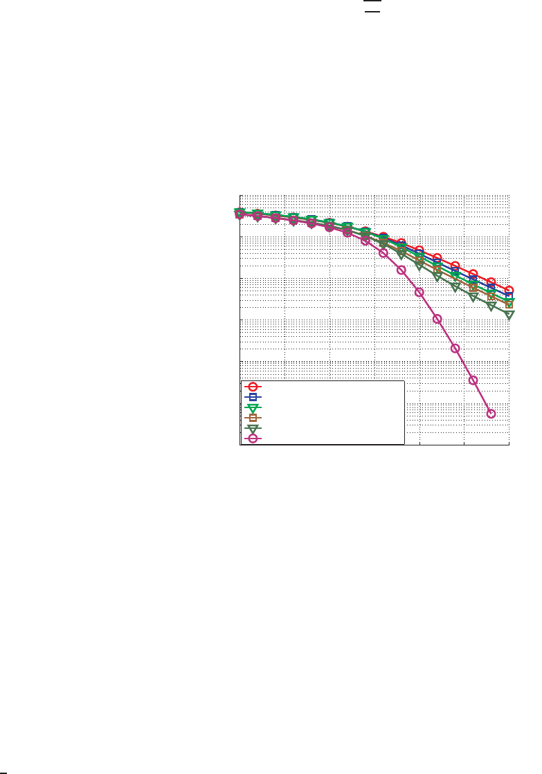
Figure 8 shows the BER results of both 16-Bit and 32 -
Bit im plementations using the MGS and GR-Plain variants.
44

Figure 9 illustrates the BER performance of the im plementa-
tion variants using CORDIC, namely GR-CORDIC a nd GR-
Hybrid. Note that the Q format
1
has b een adjusted in the
implementation to ach ieve closer to floating-point performan ce
for all the variants of implementation. Therefore, performanc e
differences are minimal between these variants. The applied Q
formats for the 16-Bit and 32- Bit variants are the following,
MGS: Q4.11 and Q5.26; GR-Plain: Q2.13 and Q5.26; GR-
CORDIC and GR-Hybrid: Q3.12 and Q3.28 .
0 5 10 15 20 25 30
10
−6
10
−5
10
−4
10
−3
10
−2
10
−1
10
0
BER
SNR (dB)
Float
16−Bit, It. 2
16−Bit, It. 4
16−Bit, It. 6
16−Bit, It. 8
32−Bit, It. 2
32−Bit, It. 4
32−Bit, It. 6
32−Bit, It. 8
uncoded BER
coded BER
Fig. 9. Coded and uncoded BER for CORDIC based implementations with
16-Bit and 32-Bit I/O data-width for different CORDIC iterations
B. Processing Time
For all the measurements in this section, the TMS320C6000
C Compiler v6.0 8 with ”-o3 -pm” optio ns has been used.
Program code and data are stored in L1RAM, with cache s en-
abled. Table IV presents the processing time in terms o f cycles
consumed by the floating -point and fixed-p oint implementa-
tions of the MGS and GR-p la in variants. The cycle counts for
CORDIC based implementation-variants, with varying number
of CORDIC iterations, are presented in Tables VI and VII.
Note that only the best case cycle counts are presented in all
the tables.
Cycle count
Implementation MGS GR-Plain
Float C 11126 89536
C 32 457 1974
C 16 443 1917
ASM 32 410 1906
ASM 16 231 1762
TABLE IV
PROCESSING TIME I N CYCLES FOR PERFORMING MMSE-SQRD USING
THE MGS AND GR-PLAIN I MPLEMENTATI ONS
1
Q format represents the fixed-point number format where the number of
fractional bits and integer bits is specified. For example, Q2.13 represents a
16-bit number with a sign bit, 2 integer bits and 13 fractional bits.
Clock cycles taken by the CORDIC implem entations have
been divided into three parts: prep rocessing, CORDIC kernel
and postprocessing. Cyc les taken by the CORDIC kerne l
depends on the number of CORDIC iterations. Total number
of cycles for executing a CORDIC operation can be given by:
l
V ec, Rot, SinCos
=l
pre
+ l
k
· n
co
+ l
post
(11)
l
V ec
, l
Rot
and l
SinCos
indicate the total number of cycles
consumed fo r performing vectoring, rotation and sincos oper-
ations respectively (described in Section V-A2). n
co
denotes
the number of CORDIC iterations. l
pre
, l
k
and l
post
represent
the number of clock cycles for preprocessing, CORDIC kernel
and postprocessing r e spectively. Table V outlines the number
of cycles consumed for performing these operation s.
Kernel Vectoring Rotation Sine Cosine
l
k
l
pre
l
post
l
pre
l
post
l
pre
l
post
Float C 493 372 372 348 348 348 496
C 32 8 38 52 38 52 38 52
C 16 8 25 29 24 25 24 26
ASM 32 6 14 16 18 20 18 20
ASM 16 6 12 14 16 15 16 15
TABLE V
PROCESSING TIME I N CYCLES FOR IMPLEMENTING THE BUILDING
BLOCKS DESCRIBED IN SECTION V-A2, SEPARATED I NTO PRE-,
POST-PROCESSING AND CORDIC KERNEL
CORDIC iterations (n
co
)
Impl. 2 4 6 8 10
Float C 45544 80764 115130 149642 184158
C 32 3243 3739 4235 4731 5227
C 16 2340 2855 3338 3830 4327
ASM 32 1759 2134 2500 2878 3247
ASM 16 1481 1855 2227 2600 2972
TABLE VI
PROCESSING TIME I N CYCLES FOR PERFORMING MMSE-SQRD USING
THE GR-CORDIC I MPLEMENTATION, (l
GR−CORDIC
)
CORDIC iterations (n
co
)
Impl. 2 4 6 8 10
Float C 33677 51515 68807 86082 103353
C 32 1684 1940 2199 2452 2708
C 16 1374 1632 1886 2142 2398
ASM 32 1137 1330 1521 1718 1904
ASM 16 953 1145 1337 1529 1721
TABLE VII
PROCESSING TIME I N CYCLES FOR PERFORMING MMSE-SQRD USING
THE GR-HYBRID IMPLEMENTATION, (l
GR−Hybrid
)
Equations for estimating the cycle counts while using GR-
CORDIC and GR-Hybrid implementations are given in Equa-
tion 12 and 13 r espectively.
45

l
GR−CORDIC
=l
Sort
+ n
V ec
· (l
V ec
(n
co
) + l
oa
)+ (12)
+ n
Rot
· (l
Rot
(n
co
) + l
oa
)
l
GR−Hybrid
=l
Sort
+ n
V ec
· (l
V ec
(n
co
) + l
om
)+
+ n
SinCos
· (l
SinCos
(n
co
) + l
om
)+ (13)
+ n
CMP Y
· (l
CMP Y
)
l
Sort
represents the processing cycles for performing one-
time sorting (wh ic h is a full sorting in a 2 × 2 MIMO
system). l
V ec
, l
Rot
and l
SinCos
indicate the cycles consumed
for vectoring, rotation and sincos operations r e spectively.
l
CMP Y
denotes the average cycle count for performing a
complex multiplication. n
V ec
, n
Rot
, n
SinCos
and n
CMP Y
rep-
resent the number of vectoring, rotation, sincos and complex
multiplication operations. The number of required complex
multiplications is the sum of all rotations listen in Table II.
The factors l
oa
and l
om
mark the overhead due to the address
and memory & address operations respectively. Note that the
cycle counts for the imp lementations using CORDIC depend
on the number of CORDIC iterations. The processing time
taken by the constant items is presented in Tab le VIII.
l
Sort
l
CM P Y
l
oa
l
om
32-Bit 151 6 4 7
16-Bit 50 5 1 9
TABLE VIII
PROCESSING TIME I N CYCLES FOR CONSTANTS
C. Discussion
Moving from a floating-point C implementation to a highly
optimized assembly code brin gs the most improvement by
a factor of 48 in MGS and the least improvement by a
factor of 31 in GR-CORDIC implementatio n (f or 2 CORDIC
iterations). The maximum and minimum reductions in terms of
cycle count when moving from a floa ting-point to a fixed-point
implementation are noticed in GR-Plain (by a factor of 45) and
GR-CORDIC (by a factor of 14) (for 2 CORDIC iterations)
respectively. In fixed-point imp lementations, maximum and
minimum difference between C 32 and A SM 16 are found
in M GS (by a factor of 2) and GR-Plain respectively (by a
factor of 1.1), other implementations vary betwe en the factors,
1.6 and 1.7. Even with 4 CORDIC iterations, the minimum
difference between MGS and G R based implementations is
found to be a factor of 5 (while using GR-Hybrid). When we
compare with GR-CORDIC, the difference rises to a factor of
8 for 4 CORDIC iterations and almost by a factor of 10 for
6 CORDIC iterations, whic h is a more fair comparison when
considerin g BER performance. However, one of the key draw-
backs of the SQRD implementation using MGS algorithm is
the ba d numerical stab ility, predom inantly due to the division
operation resulting in a high dynamic range. This results in a
degradation in BER performance at hig her dBs, which can be
noticed in M G S 16-bit implementation (Figure 8). Moreover,
the GR algorithm can be easily parallelized. This makes it
attractive for VLSI imp le mentations.
When the C64x+ DSP is ope rated at the maximum clock
frequency of 584 MHz, 16-Bit and 32-bit assembly imple-
mentations of MGS algorithm need only 0.39 µs and 0.7 µs
respectively for performing a SQRD. Among the GR based 16-
Bit assembly implementations, GR-Plain, GR-CORDIC and
GR-Hybrid (both with 6 CORDIC iterations) need 3 µs, 3.8 µs
and 2.3 µs respectively for on e SQRD operation. From the pro-
cessing time, it can be clearly seen that only the fixed-point C
and assembly implementa tions of the MGS algorithm can meet
the timing constraints while considering the most demanding
scenario of 1 µs f or one SQRD operation in LTE. However,
other 16-Bit assembly implementations become attr a ctive for
other scenarios that are less demanding, e.g. lower number
of data carrying sub-carriers, lower speed of the mobile set,
etc. For example, in the second scenario described for LTE in
Section II-B, CORDIC based implementation s can easily meet
the timing co nstraint of 8.3 µs and can be more attrac tive due
to the reusability.
Our results show th e amount of performance that nee ds
to be sacrificed when going for flexible implementations.
Though, the MGS algorithm does not offer the same amount
of flexibility in terms of implementation-variants like GR
algorithm s a nd is n umerically unstable, it is very suitable
for DSP architectures. On the other hand, SQRD implemen-
tation using CORDIC offers full flexibility, where CORDIC
iterations can be varied depending on the need. Moreover,
CORDIC algorithm can be reu sed f or implementing several
other function alities, like shown in [3].
Our an alysis has highlighted that merely increasing porta-
bility is not a solutio n for SDRs, particularly for new standards
that deman d high performance. Performance requirements
and energy efficiency have to be considered by all means.
However, this will decrease portability when adopting tradi-
tional approaches for SDR development. This calls for more
sophisticated SDR development approaches.
Library based a pproaches are highly desirable for increasing
reusability in system development. However, in order to in -
crease portability and efficiency, the components of the library
have to b e standardized for which efficient implementations
can be provided by vendors for a PE [1]. Moreover, the
components of a library should be independen t of wireless
standards and must be reusable. We have shown that using
algorithm ic kernels, like CORDIC, can enhance reusability and
offer more flexibility in imp le mentations. At the same time,
they can be implemented efficiently as well. Enhanced versions
of the implementations using the algorithmic kernel, suiting
architecture of a PE, as highlighted by GR-Hybrid implemen-
tation, can a lways be implemen te d for better performance, if
needed. Still, por ta bility effort is considerably low.
The architectur e of a PE plays a huge role in reducing
processing time and increasin g energy efficiency. T his has
been highlighted by more DSP friendly MGS algorithm c om-
pared to GR. T herefore, extreme care must be taken while
46
”mapping” an algorithm o nto a PE, particularly while using
heteroge neous hardware p la tforms. This in turn highlights the
need for quic k ”mapping” exploration at a high abstra c tion
level, presu mably at compo nent level, for reducing the time
needed for performing the exploration. We have derived
equations that acc urately estimates the cycles which could
indeed can be used by tools to perform mapping exploration
automatically.
VII. CONCLUSIONS AND OUTLOOK
In this pap e r, we have presented the analysis on flexibility
vs. efficiency tradeoffs that need to be made while developing
SDRs by using the computation in te nsive MMSE-SQRD,
which is widely used in MIM O receivers, as a case study. Two
algorithm s for performing SQRD were investigated and effi-
ciently implemented in several versions. Flexible versions of
implementations with varying degree of reusability, portability
and efficiency have bee n implemented . Though the dedicated
implementations differ in processing time by good margin
when compared to flexible implementations, efficient imple-
mentations with reusable a lgorithms can still provide flexibility
and can be used in scenarios with tight constraints, like
latency. Accurate equations which can be used for performing
constraint-aware mapping at a high abstraction level with
tool-assistance have been derived. As outlook, the analysis
of flexibility vs. efficiency tra deoffs can be continued b y
implementing more computation-intensive wirele ss p hysical
layer algorithms on different hardware architectures.
REFERENCES
[1] V. Ramakrishnan et al., “Efficient and portable SDR waveform develop-
ment: The Nucleus concept,” in Proc. IEEE Military Communications
Conf. MILCOM 2009, 2009, pp. 1–7.
[2] G. Ghosh et al., Fundamentals of LTE, 1st ed. Prentice Hall, August
2010.
[3] J. Valls et al., “The use of cordic in software defined radios: a tutorial,”
Communications Magazine, IEEE, vol. 44, no. 9, pp. 46 –50, 2006.
[4] Y. Wang et al., “Parallel MIMO detection algorithm based on house-
holder transformation,” in Proc. Int. Symp. Intelligent Signal Processing
and Communication Systems ISPACS 2007, 2007, pp. 180–183.
[5] K.-L. Chung et al., “The complex Householder transform,” vol. 45, no. 9,
pp. 2374–2376, 1997.
[6] C. K. Singh et al., “VLSI Architecture for Matrix Inversion using
Modified Gram-Schmidt based QR Decomposition,” in Proc. th Int VLSI
Design Held jointly with 6th Int. Conf. Embedded Systems. Conf, 2007,
pp. 836–841.
[7] C. K. Singh et al., “A Fixed-Point Implementation for QR Decom-
position,” in Proc. IEEE Dallas/CAS Workshop Design, Applications,
Integration and Software, 2006, pp. 75–78.
[8] R.-H. Lai et al., “A modified sorted-QR decomposition algorithm for
parallel processing in MIMO detection,” in Proc. IEEE Int. Symp.
Circuits and Systems ISCAS 2009, 2009, pp. 1405–1408.
[9] D. Wubben et al., “MMSE extension of V-BLAST based on sorted QR
decomposition,” in P roc. VTC 2003-Fall Vehicular Technology Conf.
2003 IEEE 58th, vol. 1, 2003, pp. 508–512.
[10] N. W. Gabriel L. Nazar, Christina Gimmler, “Implementation Compar-
isons of the QR decomposition for MIMO Detectionson,” 2010.
[11] C. Studer et al., “Matrix Decomposition Architecture for MIMO Sys-
tems: Design and Implementation Trade-offs,” in Conference Record of
the Forty-First Asilomar Conference on Signals, Systems and Computers
ACSSC 2007, P. Blosch, Ed., November 2007, pp. 1986–1990.
[12] I. LaRoche et al., “An efficient regular matrix inversion circuit archi-
tecture for MIMO processing,” in Proc. IEEE Int. Symp. Circuits and
Systems ISCAS 2006, 2006.
[13] Z.-Y. Huang et al., “High-throughput QR decomposition for MIMO
detection in OFDM systems,” in Proceedings of 2010 IEEE International
Symposium on Circuits and Systems (ISCAS), May 2010, pp. 1492 –
1495.
[14] P. Luethi et al., “VLSI Implementation of a H igh-Speed Iterative
Sorted MMSE QR Decomposition,” in IEEE International Symposium
on Circuits and Systems, 2007. ISCAS 2007., May 2007, pp. 1421–1424.
[15] K.-H. Lin et al., “Implementation of QR decomposition for MIMO-
OFDM detection systems,” in 15th IEEE International Conference on
Electronics, Circuits and Systems, 2008. ICECS 2008., 2008, pp. 57–60.
[16] P. Luethi et al., “Gram-Schmidt-based QR decomposition for MIMO
detection: VLSI implementation and comparison,” in Proc. IEEE Asia
Pacific Conf. Circuits and Systems APCCAS 2008, 2008, pp. 830–833.
[17] K. Mohammed et al., “A MIMO Decoder Accelerator for Next Gener-
ation Wireless Communications,” no. 99, p. 1, 2009, early Access.
[18] M. S. Khairy et al., “Efficient FPGA Implementation of MIMO Decoder
for Mobile WiMAX System,” in Proc. IEEE Int. Conf. Communications
ICC ’09, 2009, pp. 1–5.
[19] J. Eilert et al., “Efficient Complex Matrix Inversion for MIMO Software
Defined Radio,” in P roc. IEEE Int. Symp. Circuits and Systems ISCAS
2007, 2007, pp. 2610–2613.
[20] A. Irturk et al., “Architectural Optimization of Decomposition Algo-
rithms for Wireless Communication Systems,” in Proc. IEEE Wireless
Communications and Networking Conf. WCNC 2009, 2009, pp. 1–6.
[21] Z. Nikolic et al., “Design and implementation of numerical linear algebra
algorithms on fixed point DSPs,” EURASIP J. Adv. Signal Process, vol.
2007, no. 2, pp. 13–13, 2007.
[22] T. Haustein et al., “Real-time signal processing for multiantenna sys-
tems: algorithms, optimization, and implementation on an experimental
test-bed,” EURASIP J. Appl. Signal Process., vol. 2006, pp. 136–136,
2005.
[23] A. Bjoerck, “Numerics of Gram-Schmidt orthogonalization,” Linear
Algebra and its Applications, vol. 197-198, pp. 297 – 316, 1994.
[24] TMS320C64x+ IQmath Library User’s Guide, Texas Instuments, De-
cember 2008.
47
