Page 1 of 28
Pothole Detector
A Technical Report submitted to the Department of Electrical and Computer Engineering
Presented to the Faculty of the School of Engineering and Applied Science
University of Virginia • Charlottesville, Virginia
In Partial Fulfillment of the Requirements for the Degree
Bachelor of Science, School of Engineering
Steve Phan
Spring, 2020
Technical Project Team Members
Dalton Applegate
Liam Robb
On my honor as a University Student, I have neither given nor received unauthorized aid on this
assignment as defined by the Honor Guidelines for Thesis-Related Assignments
Harry Powell, Department of Electrical and Computer Engineering
Page 2 of 28
Statement of work:
Dalton Applegate
My contributions were strictly on hardware development. Most of my labor hours included
research and pouring through the datasheets of our desired components. Some decisions I have
made pertaining to this include which specific chips for each component and how to interface each
chip. I interfaced these on a bus system to make the project scalable and have picked components
to match. I produced a sensor packet that will be able to be loaded with code (MSP) and match the
Bluetooth profile of an iPhone to integrate with the app and successfully transferred accelerometer
data to the phone.
Steve Phan
The contributions I performed was designing the algorithm for the pothole detection. I also
conducted research for the mobile application in order to receive Bluetooth information from the
accelerometer. Additionally, I coded and conducted research on how to program in Swift, learning
how to add the Apple Maps API to our mobile application. I also learned how to track the user’s
location on Apple maps, displaying their current location.
Liam Robb
I helped design the algorithm for pothole detection. I have extensively researched how to
use the Swift programming language in XCode by watching several over 7 hours of tutorials online
on how to use Swift, how to create interfaces with storyboard, how to use XCode, and how to use
its library of functions including the Core Bluetooth documentation.
I also implemented code that allows us to detect all Bluetooth devices in our vicinity,
allowing us to connect to the Bluetooth chip on our PCB. Additionally, I programmed the mobile
application to add a pin whenever a specific acceleration threshold is met, marking the location of
the pothole detected.
Page 3 of 28
Table of Contents
Contents
Title Page
Statement of work: 2
Dalton Applegate 2
Steve Phan 2
Liam Robb 2
Table of Contents 3
Table of Figures 4
Background 5
Constraints 6
Design Constraints 6
Economic and Cost Constraints 6
External Standards 7
Tools Employed 7
Ethical, Social, and Economic Concerns 8
Environmental Impact 8
Sustainability 8
Health and Safety 8
Manufacturability 9
Ethical Issues 9
Intellectual Property Issues 9
Detailed Technical Description of Project 10
Project Time Line 20
Test Plan 21
Final Results 23
Costs 24
Future Work 24
References 25
Appendix 26
Page 4 of 28
Table of Figures
Figure 1 System Block Diagram………………………………………………………………....13
Figure 2. Power Distribution and Accelerometer Schematic…………………………………….13
Figure 3. MSP430 Pinout Schematic…………………………………………………………….14
Figure 4. Test Point and Bypass Schematic……………………………………………………...14
Figure 5. Bluetooth Pinout Schematic…………………………………………………………...14
Figure 6. Test Point and Bypass Schematic……………………………………………………...15
Figure 7. List of Libraries Needed for Complete Functionality………………………………....16
Figure 8. UUIDs Needed In Order to Pair…………………………………………………….....17
Figure 9. Code to Convert Accelerometer Data from Bytes to Floats…………………………...17
Figure 10. Algorithm for Pothole Detection……………………………………………………..17
Figure 11. Our Pothole Detection
Algorithm…………………………………………………….18
Figure 12. Button to Manually Add Location Pin……………………………………………… 18
Figure 13. Mobile Application Displaying the Location of Potholes We Detected……………..19
Figure 14. Gantt Chart from Initial Proposal…………………………………………………….20
Figure 15. Finalized Gantt Chart………………………………………………………………...20
Figure 16. Test Plan Flow Chart…………………………………………………………………23
Page 5 of 28
Abstract
Nothing beats the feeling of driving through your hometown or driving on a road trip,
playing sounds that remind you of your childhood and chatting with friends. Suddenly, all of that
is interrupted when you run over a pothole. You want to complain to the local government, but
you keep driving and you’ve forgotten where it was in the first place. Our solution is a pothole
detector that stores critical information, such as location and severity, and makes a map of
previously detected potholes from other users. This device incorporates accelerometers and is
connected via Bluetooth to a MSP microcontroller to process the continuous stream of data.
Simultaneously, when triggered by passing an acceleration threshold, a GPS request will be
made from the user’s smartphone to track the location of the pothole in the same moment.
Background
Potholes plague the life of the daily commuter. Some cities make an effort to fill them,
but given the ecological situation of most roads, potholes will continue to pop up or remain
unfilled due to apathy or a lack of resources from the city. Even in larger cities, potholes take
between two to three days to get fixed after they are reported [1]. Two solutions that may
mitigate this problem are improving the pothole filling effort and driver awareness to keep the
potholes from worsening due to increasing impacts. We chose this project as a means to provide
drivers and local governments with a passive way to collect information about potholes to
positively impact these two solution paths.
There have been several prototypes that detect and record potholes on the open roads. For
instance, Google has been granted a patent that uses two sensors - a GPS and a vertical
accelerometer - to automatically document nasty bumps in the road and upload the location
where the pothole was detected to the cloud [2]. There has also been an invention by Ford Motor
Company, where the technology can reduce the impact of striking potholes as part of Ford’s
controlled damping functionality [3].
In the area of pothole detection, there have been many companies and enthusiasts that
have worked on this problem. Our project is different from the ones we found online because we
are creating a sensor that attaches to the car itself with an accompanying app. Both would be sold
together as a standalone consumer product. Our goal is to create a public map that could help
local governments detect potholes faster than the current self-reporting method. Our end
customer would be citizens who feel their community isn’t efficient about fixing potholes and
municipalities who want to more efficiently deal with the issue. As far as we can tell, the only
similarity between our project and what has been done before is the detection of potholes. The
crowdsourcing of information for pothole detection and standalone product are new.
This project incorporates background knowledge from several prior courses: embedded
computer design, radio and signal processing and analysis, PCB design, analog to digital
conversion, digital data processing, network communication, program and data representation.
advanced software development, linear control systems and design, and mobile application
development. Overall, the group will be able to use previous coursework to successfully
implement this project in a timely manner.
Page 6 of 28
Constraints
Design Constraints
In regards to the hardware, the toughest constraints we faced were in regards to layout
and part sizing. Ultiboard has inherit design rules that limit the spacing between things like
whole parts as well as individual pins on a given part. All accelerometers available on Digikey
are cell phone grade, meaning among other things that they are very small (on the scale of 2-
5mm). This not only caused many problems with spacing in Ultiboard that had to be resolved,
but also proved difficult for the professionals at WWW Electronics to solder it on our board.
Initially, that was the only constraint but we later ran into self-designated constraints based on
design choices made earlier in the design process. For example, we initially thought that
Bluetooth profile selection and cross chip communication were going to be two large constraints
and we therefore selected a Bluetooth device and other chips accordingly. The Bluetooth device
was robust enough to handle any profile but that robustness came with the cost of being
complicated to understand and required code to be written to the device through a proprietary,
non GUI based IDE. This constrained our ability to use the device to only what we could come
to understand through researching its use cases. The last constraint faced was the communication
between our three chips (Bluetooth, MSP430, and accelerometer). It was initially suggested that
an inter integrated circuit (I2C) would be best given its ability to host multiple master and
servant devices on the same bus. This ease of communication came with a cost of complicated
code on the back end to support swapping between devices. In the end, we did not need to put
everything on one bus and we would have preferred to switch to a communication protocol that
was easier to debug such as Serial Peripheral Interface (SPI) or Universal Asynchronous
Receiver Transmitter (UART), however, with no board send outs left, our hardware was already
hardwired for I2C. We had to spend days debugging this communication rather than switching
styles due to this self-imposed constraint.
With respect to designing and building our mobile application, we decided to program
using Swift for an iOS device. We decided this was the best choice given that we had iOS
devices, which made testing and developing easier and more streamlined. We were also able to
use Apple’s Maps functionality, which made developing in Swift undemanding with the amount
of documentation Apple has provided [4]. Once we started developing on Swift and iOS, there
was no way for us to convert to another development environment or platform. If we had chosen
any other development platform, such as Android Studio or React Native, then it would have
been more costly or more challenging to learn given the amount of time we had. Therefore,
choosing to develop in an iOS setting gave us more flexibility to debug and test our application.
Economic and Cost Constraints
The goal of our project was to create a device that would cost less than the average cost
of maintenance on a car from pothole damage, which is around $306 [5]. The cost of parts for the
final device were $31.48. However, in the research and development portion of this project, we
spent nearly $300 in order to experiment with different devices and buy other expensive supplies
that did not go into the device such as a ground mat to protect our device during development.
Regardless, we were within the spending budget that we gave ourselves and were able to create a
Page 7 of 28
device that would have a reasonable market price. Details on what the excess money went into
and how costs could be further reduced will be discussed in the costs portion of this technical
report below.
Additionally, we wanted the development of our application to be practically free. Apple
allows this opportunity by allowing us to develop apps for free, however, without the ability to
publish it to the App Store for iOS devices. If we were to further develop our application, we
would need to pay a $99 annual fee to publish our application, as well as meeting Apple’s
guidelines for mobile applications.
External Standards
The only other standard we had to adhere to was the IPC standard for PCBs [6]. These
standards for the basis for the Design Rule Check (DRC) inside of the Multisim and Ultiboard
tools we used to design the board. These standards also display how to solder and clean the board
once printed which was important to follow to ensure the longevity of the chip.
Bluetooth was originally standardized by IEEE 802.15. However, this standard is no
longer maintained. Bluetooth technology is now overseen by the Bluetooth SIG (Special Interest
Group) which maintains the technology standard of Bluetooth device production. There is a list
of core specifications to be followed but since we will be using prefabricated Bluetooth devices,
these standards will be maintained by the producer before reaching us [7].
Tools Employed
In the creation of the sensor component of this project, we employed the use of Ultiboard
and Multisim to design and fabricate our chip. We used the design check rules in Multisim and
Ultiboard to make sure our board would meet manufacturability guidelines. After we checked
that we passed those guidelines, we used FreeDFM for final manufacturability checks on our
printed circuit board.
We developed our code for the MSP430 in Code Composer IDE, which is based on the
Eclipse IDE. We programmed our MSP in embedded C code with aide from online resources and
from resources from the Introduction to Embedded Computer Systems course. Additionally, we
programmed our MSP chip to communicate in I2C, which is different from the SPI protocol that
we learned in our introductory course in embedded. We used a variety of resources, including
online resources and guidance from Professor Delong, to accomplish a successful I2C
communication protocol.
During the development of the mobile application, we used Swift as the programming
language with XCode as the integrated development environment. We decided to program in
Swift because it allowed us to create an iOS application more easily than other tools. However,
Swift was a new language to us, so we had to learn everything, including syntax and how certain
software components were integrated. We learned how to program in Swift from YouTube and
other online tutorials. Overall, we abstracted what we learned in developing a web application
Page 8 of 28
from CS 3240, which includes debugging and finding resources, to develop a successful working
mobile application.
Ethical, Social, and Economic Concerns
An ethical and social concern for our project is the use of location data. Our project relies
heavily on the user sharing their location whenever a pothole is ran over. Some users might feel
that sharing their location data in this manner might be an invasion of privacy, or it could be
somehow used for malicious purposes. To mitigate this problem, we cannot relate the data
collected to any specific user. Therefore, each pothole found cannot be traced to any specific
individual, and we would not be collecting information on their current location or anything
similar. The application would simply be used to show where potential potholes are without
attaching that information to any specific user.
Overall, our hope with the outcome of this project is to allow local governments and
companies to repair roadways that are badly damaged and need repaving. In turn, this would
save drivers time and money from maintenance related to pothole damage, and increasing the
longevity of tires and vehicles.
Environmental Impact
Our device in itself poses no real impacts on the environment. Bluetooth devices are so
common place that their environmental impact is already minimal and decreasing as their
demand increases. However, one point of concern is the roads. Obviously, paved surfaces
already pose significant impacts to the environment and ecosystems they’re placed into or on top
of. The goal of this device is not to increase or necessarily mitigate this problem. It is simply to
make it so that if these roads are going to create environmental risk, at least they are still used for
their intended purpose and not abandoned, where they would pose no only environmental risk
but societal risk.
With this product, there may be a slight increase in a commuter’s roadway due to the
repaving of potholes but again, this is something that is already happening. The hope of this
project is to maintain our current roads so that new ones do not need to be created which would
pose a greater risk than just fixing the potholes directly.
Sustainability
Our device is not formally related to sustainability. The function of our project is to give
other users information about the location of potholes, therefore reducing maintenance costs
related to pothole and other road-related damages.
Health and Safety
Our device is not formally related to health or safety. However, we can argue that our
device can be used to make roadways safer because we are giving information to people who can
alleviate problems with road conditions. Therefore, reducing the amount of potholes and
potentially reducing traffic problems and improving driver safety.
Page 9 of 28
Manufacturability
Currently, the price to manufacture is reasonable, however, the biggest drawback to our
current design is the Bluetooth transceiver. Given that it is prefabricated, it sticks off from the
board in an unideal way and has far more components to it than is necessary for our use case. To
improve the design, it would make sense to integrate everything onto a single small, flat chip and
eliminate the unnecessary test points. This was not done initially because the scope of the project
was to create a working sensor, and not to deal with the intricacies of developing a Bluetooth
chip. Additionally, at scale with manufacturing, it would be more feasible and make more sense
to use all surface mount components, unlike the through hole components we used for testing
and developing.
With any mobile application, the ability to expand and build on the application is crucial.
If this project were to go into full production, the mobile application would need to be more
refined. This requires having a larger development team with specialized skills to perfect the
application from bugs and usability. We would also need a team of developers to maintain our
application after it is published to address environment changes to hardware and bugs in the
software.
Ethical Issues
The goal of this device is to create a robust database of potholes in a given area to aid in
the repair of these potholes or integrate into a mapping algorithm as an early detection and
avoidance device. The current system in place involves individuals self-reporting the potholes
direct to companies. In order to unload this burden from the consumer, our sensor and
application aims to do this passively. There is an ethical issue when we track the user’s location.
Even though we would not be providing the location to anyone, some users might feel unsafe to
learn that a device could pinpoint their location. As LaFrance wrote in The Atlantic, “Sometimes
it’s just that the people who are designing the gizmo don’t even think in terms of privacy,” he
told me. “They just think: More data is always better. In their minds, it’s just, ‘We may not know
what we’re going to do with that data.’” [8]. Therefore, we would have to make the location data
anonymous to prevent anyone from using it for any other purpose. The current app does not have
a persistent database, as it is just a proof of concept, and as a result, does not associate any data
between the phone running the application and the stored locations. The individual potholes are
also not linked so with fully populated database, individual routes would not be traceable. The
only discernible information would be increased intensity of detections around heavy pothole
areas which is exactly the information we wish to provide. Ultimately, we believe that it is in the
automotive industry’s best interest to keep cars well maintained, and local cities to keep their
roads safe and drivable.
Intellectual Property Issues
The first patent we examined is titled ‘Road health (pothole) detection over wireless
infrastructure’. Looking at the patent’s claims, ones that stand out are the following: ‘1. a motor
vehicle, comprising: a road condition sensor configured to detect a hazardous condition of a road
on which the motor vehicle is traveling; a global positioning system configured to detect a global

Page 10 of 28
position of the motor vehicle; and an electronic processor communicatively coupled to the road
condition sensor and to the global positioning sensor” [9]. Based on the language of the patent,
an example of which is “the motor vehicle of claim 1 wherein the road condition sensor
comprises an accelerometer,” the claims are dependent on other claims [9]. The patent discussed
here is similar to our project, where an accelerometer is used and an electronic processor is able
to send a receive information from the sensor.
The second patent we examined is titled ‘Pothole detection in the vehicle’. Looking at the
patent’s claim, it claims that “Method for creating a digital map as a basis for a driver assistance
system, which is set up to assist a driver in dealing with road damage ( 60 ), comprising: -
detecting road damage ( 60 ) on a street ( 13 ) with a vehicle ( 2 ); - Capture a position ( 22 ) of
the vehicle ( 2 ), if the road damage ( 60 ) is detected; and - entering a card information ( 58 )
into the digital map in which the detected road damage ( 60 ) of the recorded position ( 22 )
assigned” [10]. Based on the language of the patent, an example of which is “the method of
claim 2, wherein sending the card information ( 58 ) takes place wirelessly, the claims are
dependent claims [10], the claim in question is dependent. The patent discussed here is similar to
our project, where a digital map is created when road damage is detected.
The third patent we examined is titled “ Mobile pothole detection system and method.”
Looking at some of the patent’s claims, it claims the following: “A system for analyzing a
surface subject to degradation, comprising: a sensor configured to acquire at least one image of a
surface” [11]. Based on the language of the patent, an example of which is “the system of claim
1, wherein the sensor comprises: at least one of a camera or accelerometer,” the claim is
dependent [11]. The patent discussed here is similar to our project, where accelerometer data is
collected and sent wirelessly, getting the coordinates of the surface abnormality.
Based on our findings of these three patents, our project is not patentable. There are too
many claims associated with different patents to make our project unique enough to be
patentable.
Detailed Technical Description of Project
Our capstone project consists of a Bluetooth Low Energy (BLE) enabled sensor
component and a companion iOS application with integrated Apple Maps features. The sensor is
made up of a Texas Instruments MSP430G2553 microprocessor, an ESP32 BLE dual core
microprocessor, and an AIS328DQ three axis accelerometer communicating through an Inter
Integrated Circuit (I2C) communication protocol. The remaining components on the board
pertain to operating the MSP430, power bypassing each chip, and distributing power. As for the
power distribution, an LT1121 Low Drop Out (LDO) regulator is used to step the 5V USB
supply to the 3.3V required by each chip. A full list of components is located in the appendix.
The three chips on our board are hardwired on the Printed Circuit Board (PCB) for the
I2C interface. The MSP430 is responsible for running the C code, which is the foundation for the
I2C protocol, and transferring the data from the accelerometer to the phone. The MSP430
initializes by writing to registers within the BLE chip and the accelerometer, setting them to on
Page 11 of 28
and operate as servants to the MSP430 master’s instruction. The MSP430 then sends alternate
pulls and pushes to the two servant chips. Before each interaction, the MSP430 sends a START
signal which consists of a LOW digital signal on the SDA line (data) of the I2C interface while
the SCL line (clock) remains HIGH. Each servant device then ‘listens for its own unique, factory
defined I2C address. If a device receives its own address, it sends an acknowledge signal (ACK)
and awaits further data or begins to transmit data to the master. For each pull, the MSP430 sends
an address followed by a sub-address to the accelerometer which requests the X axis acceleration
data from the corresponding register inside the accelerometer. Once the master receives the
contents of this register, it sends a negative acknowledgement (NACK) followed by a STOP
signal (LOW to HIGH on SDA while SCL is held HIGH) to end the communication. The
MSP430 then writes this data to one of its own registers as RAM as it only needs to store it long
enough to pass it to the BLE chip before pulling new data from the accelerometer. On the other
side, similar commands push the data from the register on the MSP430 and write it to the BLE
chip. The BLE chip then pipes this data directly to the mobile application in real time as to not
miss a potential detection. The mobile application waits for a certain acceleration threshold to be
met, placing a pin when a vertical acceleration passes that threshold.
The components we used to build the sensor are as follows:
● ESP32 Dual Core Bluetooth and WiFi enabled microprocessor (1)
● MSP430G2553 microprocessor (1)
● AIS328DQTR 3 axis accelerometer (1)
● LT1121 8 in DIP LDO voltage regulator (1)
● Micro USB connector (1)
● Printed Circuit Board (1)
● Plastic Case (1)
● Test pins (8)
● Resistors
○ 300Ω (1)
○ 47kΩ (1)
● Headers
○ 14 pin JTAG (1)
○ 20 pin DIP (1)
○ 19 pin in-line (2)
● Capacitors
○ 22μF (2)
○ 10μF (1)
○ 1nF (1)
○ 1μF (4)
The next section outlines substantial design decisions and tradeoffs that were made
through the design process of this project. Our major design decisions include the choice of our
microprocessor, the Bluetooth device, the accelerometer, the chip communication protocol, and
the power supply for the hardware. For software, we chose to implement on Apple devices given
Page 12 of 28
that we all prefer those devices over Android. Therefore, we also chose to use Swift and the
Apple maps API to design our app given that we were working with iOS enabled devices.
The choice of chips provided the biggest tradeoffs. For example, we chose the 20 pin DIP
package MSP430G2553. We were very familiar with the use of this chip from the Intro to
Embedded Computing course and the DIP package made it easy to solder in or replace on the
board. However, this limited the number of ports we had access to and did not allow us to utilize
features that come with other processors such as the newer MSP432 or myRIO. This package
also did not have the flat form factor that would be ideal for a final project, though it was ideal
for testing. The most impactful results of this trade off was our choice of communication
protocol. The lack of ports led us to heed the recommendation of utilizing the I2C protocol over
the Serial Peripheral Interface (SPI) due to the ability to communicate with multiple masters and
servants all on one bus or port. With this choice, we traded simplicity of hardware for complexity
of software. We achieved 2 line communication but spent likely up to 100 man hours coding and
debugging in a complex manner that we had no prior experience with. This was an unnecessary
trade off however and probably would not be repeated if this device was designed again. The
accelerometer we chose was initially too small to be soldered on by hand correctly, even by the
professionals at WWW electronics. We opted for a larger accelerometer for a better package.
Finally in terms of hardware, we selected a very complex Bluetooth transceiver. This choice was
driven by the initial thought that we would need to have a variety of Bluetooth profiles to choose
from. We eventually discovered that any chip that supported BLE would be viable but it was too
late to switch to a chip that did not require programming like the ESP32 did. In the end, it
worked out fine as we were able to utilize the USB port on this device for power.

Page 13 of 28
Figure 1. System Block Diagram
Figure 1 shows the final block diagram for our system, with only some last minute
changes in the way of the battery, database, and mapping API. The four lines on the chip
represent the 2 lines required for I2C (SDA and SCL) as well as power and grounding nodes
shared by the 3 chips.
Figure 2. Power Distribution and Accelerometer Schematic

Page 14 of 28
Figure 3. MSP430 Pinout Schematic
Figure 4. Test Point and Bypass Schematic
Figure 5. Bluetooth Pinout Schematic

Page 15 of 28
The schematic choices were fairly simple. Each chip needed grounding, power from a
3.3V line, an SDA data line, and an SCL clock line. Additionally, bypass capacitors or resistors
were added as specified in the recommendations of the manufacturer of each chip. The BLE chip
itself had many more black boxed components within it that performed any functions it needed.
The MSP430 and the accelerometer both had all of their spare pins pull out for testing or adding
extra functionality later if we discovered a feature we wanted after the last board send out such
as using the accelerometer’s interrupt generators or the MSP430’s GPIO pins. Finally, the
accelerometer’s CS pin was tied high to lock it into I2C mode (additionally, it had internal pull
up resistors on the SDA and SCL lines which is why they are not present in the schematic) and
the SA0 pin was tied low externally to set the last address bit to 0 (this feature allows two of the
same accelerometer on the same I2C bus but we did not need to utilize this feature).
Figure 6. Test Point and Bypass Schematic
The most important decision of the layout was how to wire the accelerometer. We
received consistent Design Rule Check (DRC) errors due to the proximity of the pins on the chip
to themselves and therefore saw these errors when wiring as well. Power was also a concern as
10mil power lines were the largest size that could be used on the accelerometer. As is likely
apparent, the only way for power to get from the source in the bottom left to the rest of the chip
is through those 10 mil lines which is likely what lead to our power distribution problem at the
last minute that was fixed by placing the 3.3V source elsewhere. Using surface mount parts for
the regulator and accelerometer also proved challenging for wiring due to the fact that the ground
plane was on the copper bottom. The orientation of the MSP430 and the accelerometer was only
important as to have as few lines crossed as possible because they were packed so tightly. The
BLE chip however had to be placed in the upper part of the board as it took up a lot of space and
needed an exclusion zone so that the board would not affect the antenna. In an attempt to keep
size low, the edges of the board were brought in, meaning that some wires had to cut across the

Page 16 of 28
board through the middle. One of these ended up cutting the ground plane but this was
minimized as much as possible while avoiding the other traces.
Our major issues center around the I2C code and the power distribution. The power was
switched to 5V USB instead of a 9V battery to bypass the 10 mil traces near the accelerometer.
The second issue was ensure that I2C communication was being performed correctly. This could
not be fixed with a design change since the hardware was set in stone. We eventually overcame
this after several hours of debugging.
Our next subsystem is the mobile application. We programmed our mobile application in
Swift for an iOS device. We chose Swift because it quickly allowed us to debug and program to
an iOS device. If we had chosen any other programming interface, including React Native or
Android Studio, we would have needed to overcome a steeper learning curve with respect to
React Native, or buy a new mobile device, which could have been at least a couple hundred
dollars.
We decided to use Apple Maps over an alternative, such as Google Maps, because Apple
Maps is more widely supported in Swift than Google Maps. It was easier to find documentation
that helped with our functionality. This includes Bluetooth connectivity to the Bluetooth chip on
our PCB, placing pins on the map whenever a pothole was detected, and showing the user’s
current location.
We used a variety of software libraries that were essential for the complete functionality
of the mobile application, as shown in Figure 7. The Mapkit library was needed for the usage of
Apple Maps. We used the CoreLocation library to show and access the user’s location on the
map. Additionally, we used the CoreBluetooth library to be able to connect to the Bluetooth chip
in the direct area of the mobile device. Finally, we used the CoreMotion library to get
acceleration data from the accelerometer and process it with our algorithm.
Figure 7. List of Libraries Needed for Complete Functionality
To connect the phone to the Bluetooth chip, we had to figure out the UUIDs of the
Bluetooth chip. We found the device UUID and the characteristic UUID, as shown in Figure 8
below.

Page 17 of 28
Figure 8. UUIDs Needed In Order to Pair
We used the following snippet of code, as shown in Figure 9, to convert the
accelerometer data from bytes to floats. This allowed us to interpret the raw data from the
accelerometer into a readable format for both the user and for our understanding of different
vertical acceleration thresholds.
Figure 9. Code to Convert Accelerometer Data from Bytes to Floats
Next, Figure 10 shows the overall flow of our algorithm, and Figure 11 shows our
algorithm in code that places a pin when a pothole is detected. Logically, if we have a vertical
acceleration that is greater than 10 meters per second squared, we technically have some sort of
substantial road condition. Once this threshold is met, we place a pin directly over the user’s
current location, and having it persist on the map after the user moves away. We also gather the
location data, including longitude and latitude, to accurately give us the address of that pothole.
Figure 10. Algorithm for Pothole Detection

Page 18 of 28
Figure 11. Our Pothole Detection Algorithm
Since not every individual would like to have their location data used, we added a manual
button that would allow users to pinpoint the location of a pothole, as shown in Figure 12. In
theory, this would allow us to reach a wider range of users, so we can gather as much data as we
can.
Figure 12. Button to Manually Add Location Pin
The results of our final mobile application are displayed in Figure 13 below. The red pins
show the approximate geo-location of each pothole we found.

Page 19 of 28
Figure 13. Mobile Application Displaying the Location of Potholes We Detected

Page 20 of 28
Project Time Line
Figure 14. Gantt Chart from Initial Proposal
KEY
_________
_________
_________
_________
_________
_________
_________
Design
Time
Testing
Time
Time for
Each Part
Implement-
ation Time
School
Breaks
Project
Deadlines
Date of
Today
Figure 15. Finalized Gantt Chart
Page 21 of 28
The main difference between the two Gantt charts presented above is that the integration
portion was extended and pushed back to allow for delays in receiving parts and boards. All of
the tasks except for the final integration were easily parallelized as Steve worked on the mapping
portion of the app, Liam researched and developed the BLE communication, and Dalton
completed the sensor hardware. Once each of these were completed, they could also be tested
individually so that they were not delayed by the other tasks. Each task was also designed to be
integrated slowly. For example, sample data could be read over Bluetooth before the C code was
finished as junk data and the map and Bluetooth apps could be integrated whenever given they
were developed on the same platform. This flexibility allowed us to put extra time towards parts
of the design process that took longer than expected. This also allowed us to perform our
secondary rolls as Steve took charge of integrating the application and managing the
documentation and organization of the team, Liam used his knowledge of Bluetooth to debug the
hardware and C code, and Dalton gathered appropriate data to ensure correct functioning after
integration.
In terms of long term dates, our goals were to have software finished at the same points
as board submissions and part orders to ensure that both sides were progressing along with the
hardware. To keep up with the hardware deadlines, we were sure to send something out with
each deadline to be on the safe side. The midterm design review and Thanksgiving break were
also used as major progress goals. We set all initial layouts and code to be done by the design
review with the final project finished around Thanksgiving to leave time for testing. This was
important to have this extra time as some steps got delayed and this time was used to course
correct.
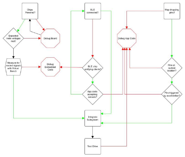
Test Plan
Our test plan consisted of three main sections: testing the hardware, testing the Bluetooth
capabilities, and testing the data tracking. We were able to do most of these in parallel as they
neared completion to ensure that our integration testing portion would go more smoothly, as we
would know that each subsystem is functioning properly. To test the hardware, we employed the
use of the Virtual Bench and Code Composer Studio’s debug mode. After checking our
individual parts for any visible damage and soldering all the components onto the board, we
tested our node voltages and current draw to ensure that each chip would be drawing the
necessary power. We first did this with the chips removed from their headers to make sure that
the chips would not be damaged by unexpected high voltage. We tested node voltages with
different input voltages from the virtual bench to decide what final power supply would be best
before switching to testing with a 9V battery to ensure that the regulator was supplying the
expected 3.3V. We reperformed this test after switching to the BLE power as the main driver.
Once everything received power and the embedded code was written, we began to check the
signals that were on the SDA and SCL lines at certain times to check if the START, STOP, and
address signals were being sent appropriately. This confirmed that what we were seeing on Code
Composer matched what was occurring on the board. From here, we were able to test the I2C
code in Code Composer to verify whether the accelerometer and BLE chip were receiving our
Page 22 of 28
communication. This was done by checking what happened as the C code entered either the
transmit or receive interrupt that was generated when data was placed onto the receive or
transmit buffer in the MSP430’s hardware. Once it was verified that the signals were being
acknowledged, we could check the registers on the MSP430 to see what data had been received
and stored. The hardware was then ready for integration testing.
Once the application was complete, we began to test the connection between the
hardware and software. To beta test the BLE connection, we downloaded a simple third party
application that could create BLE connections and show the data as a hex number that was being
received. This allowed us to ensure that something was being sent out of the sensor. Once this
was confirmed and we matched the UUID of our device to the code, we began to search for our
BLE signal within our own app. As shown in the test plan, we had to tweak things on both the
application side and embedded side until we were receiving data on the app. We first tested this
by pairing with a Bluetooth scale to see we could receive data. When we verified we were
receiving data from the scale, we tweaked how the data was being received until it appeared
reasonable.
Once we established a Bluetooth connection, we got to work on the map functionality. To
test that the pins were being placed on the correct location, we placed a pin at our current
location hoping to see if it was accurately placed when a button was pressed. Next, we traveled
to a different location, placing a pin to mark our location. When we saw that this functionality
was working, we developed an algorithm to place pins when a pothole was detected. We tested
this feature by shaking the accelerometer, expecting that a pin would be placed at our current
location. When we proved this algorithm and functionality was complete, we did a field test with
our entire system.
Finally, we were able to take the sensor on test rides in a vehicle. We selected a few deep
potholes that we knew of in Charlottesville to see how our sensor would react to them. Initially,
we drove over these potholes using a third party application to get a sense of what the
acceleration response would be. This is how we set our initial threshold values for what a pothole
may look like. We also performed calculations on expected acceleration of a car hitting a pothole
at 35mph to get a general idea of other potholes that we didn’t test but that we wanted the sensor
to be able to detect anyway. Next, we drove over the same potholes to have the sensor detect
them. We compared the response of a pothole to normal driving acceleration such as driving up
or down hill as well as taking sharp turns that may affect detection. We then tweaked the
thresholds and drove through the course a few more times until we were happy with the detection
rate.
Page 23 of 28
Figure 16. Test Plan Flow Chart
Final Results
In our proposal, we define success as achieving all of the following: 1) Device is
triggered when it hits a pothole 2) Device records pothole severity 3) Device records GPS
location of pothole 4) Device communicates over Bluetooth to a smart device. We achieved all
of our metrics for success based on the results we were able to achieve.
Above all else, our device is able to detect potholes in normal driving conditions. The
success of this device includes a baseline working mobile application and a fully functioning and
communicating BLE enabled motion sensor. This device was intended to be a proof of concept
given the time constraints and therefore functions as such. As a result of this, there is no data
persist present in the application and little to no user interface.
That being said, there is a very useful GUI derived from the Apple Maps API that forms
the backbone of the application which still provides useful information (location and intensity of
the potholes) that we originally intended for the app. Our app was successful in pinpointing the
location of potholes and other major road conditions, but would sometimes pin locations that had
no visible potholes because the threshold for acceleration was surpassed. Further testing and
categorization would be effective in minimizing future false positives. Otherwise, our application
was successful in connecting to the Bluetooth to receive information, and displaying the user’s
location.
In regards to the hardware, the sensor was successful in terms of the on board
communication protocol but, in our opinion, fell short in terms of power consumption and form
Page 24 of 28
factor. By the time of the final board send out, all of the necessary components were on the board
and set up properly, however many unnecessary pins and extra space were left on the board.
Given an opportunity of one or two more board iterations, the form factor could have been
greatly improved in terms of shape, size, and to eliminate capacitances and poor grounding
created by some wire placements. This also meant that we had to use a bulky casing to protect
the chip as opposed to using a sleek and small case that could be placed more discreetly in the
vehicle. As for the power, there was a last minute issue in which the battery was unable to power
the BLE chip. the power indicator showed that the BLE chip as well as the rest of the board were
receiving the expected power, yet no signals could be found coming from the accelerometer. To
solve this, we used the built in USB power on the BLE chip to power the board. The 3.3V pin of
the BLE chip was attached the main power distribution network of the chip so by powering the
BLE chip from the USB, we could in turn power the whole board without a battery. However,
this limited the versatility of the sensor overall as it now needs to be plugged into a 5V USB plug
in the interior of the vehicle rather than near the wheel as was the original intention.
Costs
Our total costs were around $300.00 which included all parts required to build a sensor as
well as tools for research and development. The actual price point of the sensor was $30.00. We
have found that one sensor is sufficient to detect potholes, also making it much easier to install
device. The most expensive piece of this sensor is the BLE chip. Ideally, if the chip were
manufactured on the scale of 10000, this chip would be best integrated onto the rest of the board
which could reduce costs significantly. Additionally, soldering all components at scale as surface
mounts could be done very cost effectively, however this would not impact the cost as much as
integrating the BLE chip. However, on the application side, money would need to be invested to
maintain an app developer status to keep the permanence of the application. Still, at scale, this
cost would not affect the overall pricing and could be maintained for free to download on the app
store.
The cost to develop our mobile application is nothing. However, if we wanted to ever
publish our application, we would need to pay a $99 developer fee, as well as adhering to safety,
performance, business, design, and legal guidelines set by Apple [12].
Future Work
There are several facets we would like to build upon in the case of any future work. First,
as stated in other places in this report, the board could be stripped of all extra test points and have
all components integrated into one board as opposed to the separate board that the BLE chip
resides on currently. Additionally, we would like to experiment with other board designs
including different hardware communication protocols such as SPI and UART to see if there is a
more efficient method.
In future iterations of the mobile application, we could make it so that it could be
compatible with other devices, including Android and Windows. This could mean developing
another version of the application in Android Studio, React Native, or a similar programming

Page 25 of 28
language and integrated development environment. We could also look into using Google Maps,
which is more widely used than Apple Maps on many devices around the world, while
considering the tradeoffs these two APIs have in terms of usability and ease of development [13].
References
[1] “Pothole Repair,” Virginia Department of Transportation, [Online], Available:
https://ddot.dc.gov/potholes. [Accessed: 14-Sep-2019].
[2] Thing and Person, “Google Patents System That Detects Potholes,” Digital Trends, 26-Aug-
2015. [Online]. Available: https://www.digitaltrends.com/android/google-pothole-detection/.
[Accessed: 14-Sep-2019].
[3] Innovative Pothole Detection System Irons Out the Bumps for All-New Ford Focus Drivers |
Ford of Europe | Ford Media Center, 28-Jun-2018. [Online]. Available:
https://media.ford.com/content/fordmedia/feu/en/news/2018/06/28/innovative-pothole-detection-
system-irons-out-the-bumps-for-all-.html. [Accessed: 14-Sep-2019].
[4] Apple Inc, “Integrating with Apple Maps,” Maps - Apple Developer. [Online]. Available:
https://developer.apple.com/maps/. [Accessed: 12-Dec-2019].
[5] “Potholes and Vehicle Damage,” AAA Exchange. [Online]. Available:
https://exchange.aaa.com/automotive/automotive-trends/potholes-vehicle-damage/. [Accessed:
13-Dec-2019].
[6] “IPC Checklist for Producing Rigid Printed Board Assemblies,” Association Connecting
Electronic Industries [Online]. Available: http://www.ipc.org/4.0_Knowledge/4.1_Standards/
PCBA-Checklist.pdf. [Accessed: 14-Dec-2019]
[7] “Core Specifications,” Bluetooth Technology Website. [Online]. Available:
https://www.bluetooth.com/specifications/bluetooth-core-specification/. [Accessed: 25-Sep-
2019].
[8] LaFrance, A. (2019). The Creepy Thing About Self-Driving Cars. [online] The Atlantic.
Available at: https://www.theatlantic.com/technology/archive/2016/03/self-driving-cars-and-the-
looming-privacy-apocalypse/474600/ [Accessed 22 Sep. 2019]
[9] H. A. Troemel Jr, M. R. Stelts, “Road health (pothole) detection over wireless infrastructure,”
United States Patent 20180040090A1, July 8, 2017.
[10] B. Uhrmeister, “Pothole detection in the vehicle,” German Patent DE102014214729A1,
July 25, 2014.
[11] J. Bridgers, T. Chiang, “Mobile pothole detection system and method,” WIPO
WO2014197448A1, June 03, 2013.
[12] Apple Inc, “App Submissions - App Store,” Apple Developer. [Online]. Available:
https://developer.apple.com/app-store/submissions/. [Accessed: 14-Dec-2019].

Page 26 of 28
[13] J. Dove, “Apple Maps vs. Google Maps: Which One Is Best for You?,” Digital Trends, 09-
Dec-2019. [Online]. Available: https://www.digitaltrends.com/mobile/apple-maps-vs-google-
maps/. [Accessed: 15-Dec-2019].
Appendix
Manufacturer
Part
Number
Description
Parts
Received
Parts
per
Sensor
Price
Total
Spent
Total
Sensor
Cost
Espressif
Systems
ESP32-
DEVKITC-
32D-F
Bluetooth Transceiver
4
1
$ 10.00
293.17
31.48
Broadcom
Limited
HLMP-
3519-F0002
LED
10
0
$ 0.50
Stackpole
Electronics
Inc
CF14JT300
R
Resistor
10
1
$ 0.10
On Shore
Technology
Inc.
302-S141
JTAG
6
1
$ 0.32
ACL Staticide
Inc
6672436
Ground Mat
1
0
$ 35.00
Adam Tech
HPH1-A-19-
UA
Header Pins
10
0
$ 1.03
SCS
ECWS61M-
1
Ground Strap
5
0
$ 5.85
Pimoroni Ltd
PIM456
Accelerometer Breakout
5
0
$ 5.03
Texas
Instruments
LM1117MP
X-1.8/NOPB
Regulator
5
1
$ 1.10
TDK
Corporation
FG11X7R1
C226MRT0
6
Capacitor
10
2
$ 0.86

Page 27 of 28
TDK
Corporation
FG28X5R1
E106MRT0
6
Capacitor
10
1
$ 0.46
AVX
Corporation
SR211A101
JARTR1
Capacitor
45
0
$ 0.33
Murata
Electronics
RDER73A1
02K2M1H03
A
Capacitor
10
1
$ 0.65
KEMET
C330C105K
5R5TA7301
Capacitor
10
4
$ 0.55
Stackpole
Electronics
Inc
CF14JT47K
0
Resistor
10
2
$ 0.10
Vishay BC
Components
K120J15C0
GF5TL2
Capacitor
10
0
$ 0.26
TDK
Corporation
FG18X7R1
H474KRT06
Capacitor
10
0
$ 0.36
Vishay BC
Components
K220J15C0
GF5TL2
Capacitor
10
0
$ 0.26
On Shore
Technology
Inc.
ED20DT
MSP Header
7
1
$ 0.26
Texas
Instruments
MSP430G2
553IN20
MSP
7
1
$ 2.69
Sullins
Connector
Solutions
PREC019S
AAN-RC
Header Pins
8
2
$ 0.42
STMicroelectr
onics
AIS328DQT
R
Accelerometer
4
1
$ 10.46

Page 28 of 28
Keystone
Electronics
1025-7
Battery Connector
4
0
$ 1.93
Keystone
Electronics
232
Battery Connector
4
1
$ 0.48
Keystone
Electronics
2480
Battery Connector
4
0
$ 1.61
MPD (Memory
Protection
Devices)
BC3AAW
Battery Connector
4
0
$ 1.77
NDK America,
Inc.
NX2016SA-
24M-
EXS00A-
CS08891
Oscilator
1
0
$ 0.64
Abracon LLC
AMCA31-
2R450G-
S1F-T3
Anntena
1
0
$ 0.55
