
DETECTING POTHOLES USING IMAGE PROCESSING
TECHNIQUES AND REAL-WORLD FOOTAGE
Submitted in partial fulfillment of the requirements for the award of
Bachelor of Engineering Degree
in
Computer Science and Engineering
by
Naman Rathore R (38110350)
Naman N Jain(38110349)
DEPARTMENT OF COMPUTER SCIENCE AND ENGINEERING
SCHOOL OF COMPUTING
SATHYABAMA
INSTITUTE OF SCIENCE AND TECHNOLOGY
(DEEMED TO BE UNIVERSITY)
Accredited with Grade “A” by NAAC
JEPPIAAR NAGAR, RAJIV GANDHI SALAI,
CHENNAI – 600 119
APRIL 2021
i

SATHYABAMA
INSTITUTE OF SCIENCE AND TECHNOLOGY
(DEEMED TO BE UNIVERSITY)
Accredited with ―A‖ grade by NAAC
Jeppiaar Nagar, Rajiv Gandhi Salai, Chennai – 600 119
www.sathyabama.ac.in
DEPARTMENT OF COMPUTER SCIENCE AND ENGINEERING
BONAFIDE CERTIFICATE
This is to certify that this Project Report is the bonafide work of Naman Rathore R
(38110350),Naman N Jain38110349who carried out the project entitled “DETECTING POTHOLES
USING IMAGE PROCESSING TECHNIQUES AND REAL-WORLD
FOOTAGE” under my supervision from NOVEMBER 2019 to APRIL 2020.
Internal Guide
Dr. V. Nagarajan
Head of the Department
Dr. S. VIGNESWARI, M.E., Ph.D.,
Submitted for Viva voce Examination held on
Internal Examiner External Examiner
ii
iii
DECLARATION
I Naman Rathore R (38110350) hereby declare that the Project Report entitled “DETECTING
POTHOLES USING IMAGE PROCESSING TECHNIQUES
AND REAL-WORLD FOOTAGE” done by me under the guidance of Dr. V .
Nagarajan is submitted in partial fulfillment of the requirements for the award of
Bachelor of Engineering degree in Computer Science and Engineering.
DATE:
PLACE: CHENNAI SIGNATURE OF THE CANDIDATE
iv
ACKNOWLEDGEMENT
I am pleased to acknowledge my sincere thanks to Board of Management of
SATHYABAMA INSTITUTE OF SCIENCE AND TECHNOLOGY for their kind
encouragement in doing this project and for completing it successfully. I am grateful
to them.
I convey my thanks to Dr. T. SASIKALA M.E., Ph.D., Dean, School of Computing,
also Dr. S. VIGNESHWARI M.E., Ph.D., and Dr. L. LAKSHMANAN M.E., Ph.D.,
Heads of the Department of Computer Science and Engineering for providing me
necessary support and details at the right time during the progressive reviews.
I would like to express my sincere and deep sense of gratitude to my Project Guide
Dr. V. Nagarajan for her valuable guidance, suggestions and constant
encouragement paved way for the successful completion of my project work.
I wish to express my thanks to all Teaching and Non-teaching staff members of the
Department of Computer Science and Engineering who were helpful in many
ways for the completion of the project.
v
ABSTRACT
Roads are the main mode for transportation, now a days. As we use roads heavily
and frequently it sometimes leads to potholes. Environmental factors also leads to
potholes in several ways. These potholes are main reason for many accidents. A
Scheduled and proper maintenance is required where we need to monitor each and
every road. AS this maintenance of all the roads at a time is not possible because it
is not easy to monitor every single place or just because people ignore to check
which causes formation of potholes that causes unnecessary traffic and many of
accidents. To monitor all the roads this project for pothole detection using image
processing techniques implemented. To test the performance of the proposed
system is going to be implemented in a linux environment using Open CV Library.
Techniques of Image processing which detects the potholes on roads and save the
data of pothole for road maintenance department. This helps in keeping manual
labour to the minimum number. Canny Edge Detecting technique and alone with the
Contour Detecting Technique are techniques of Image Processing we use in the
proposed system. Hough transformation technique in the end gives effective output
of potholes, very accurately.
vi
Table of Contents
CHAPTER NO.
TITLE
PAGE NO.
ABSTRACT
LIST OF FIGURES
v
viii
1
INTRODUCTION
1
1.1 POTHOLE DETECTION
1
1.2 OBJECTIVE
2
1.3 MOTIVATION
2
2
LITERATURE SURVEY
4
2.1
AUTOMATIC POTHOLE DETECTION
2.2
AUTOMATIC DETECTION AND
NOTIFICATION OF HUMPS ON ROADS
4
5
2.3
SMART SENSING OF POTHOLES
AND OBSTACLES 6
2.4
DETECTION AND NOTIFICATION
OF POTHOLES AND HUMPS 7
2.5
AN APPROACH FOR REAL-TIME
ROAD DEFORMATION DETECTION 8
2.6
POTHOLES DETECTION BASED
BLOB DETECTION METHOD 9
3
METHODOLOGY
12
3.1 EXISTING SYSTEM
12
3.1.1 Disadvantages
12
3.2 PROPOSED SYSTEM
12
3.2.1 Advantages
13
3.3 FLOW CHART
14
3.4 HARDWARE REQUIREMENTS
15
3.5 SOFTWARE REQUIREMENTS
15
3.5.1 Linux
15
3.5.2 Ubuntu
16
3.5.3 Ubuntu Variants
16
3.5.4 Python
17
3.6 SYSTEM DESIGN
18
3.7 ALGORITHM
19
3.8 CANNY EDGE DETECTION ALGORITHM
19
3.8.1 Gaussian Filter
19
3.8.2 Intensity Gradient
20
3.8.3 Non-Maximum Suppression
21
vii
3.8.4
Double Threshold 22
3.8.5
Edge Tracking By Hysteresis 23
3.9
IMAGE THRESHOLDING 24
3.9.1
Otsus’s Method 24
3.10
HOUGH TRANSFORM 25
3.10.1
Theory 26
3.10.2
Example 1 27
3.10.3
Example 2 29
4 RESULT AND DISCUSSION 30
5 CONCLUSION AND FUTURE ENHANCEMENT 33
5.1
CONCLUSION 33
5.2
FUTURE ENHANCEMENT 33
REFERENCES 34
APPENDIX 35
A.SOURCE CODE 35
B. SCREENSHOTS 37
C. PUBLICATION WITH PLAGIARISM REPORT 40
viii
LIST OF FIGURES
FIG NO. FIG TITLE PAGE NO.
3.1
FLOW CHART 14
3.2
GAUSSIAN SMOOHING 20
3.3
HOUGH TRANSFORM 27
3.4
EXAMPLE 1 28
3.5
RENDERING OF TRANSFORM RESULTS 29
4.1
ORIGINAL IMAGE 30
4.2
PREPROCESSING IMAGE 30
4.3
COLOR SEGMENTATION IMAGE 31
4.4
EDGE DETECTION IMAGE 31
4.5
SAVED DATA IMAGE 32
1
CHAPTER 1
INTRODUCTION
1.1
POTHOLE DETECTION
Potholes are bowl-shaped openings on the road that can be up to 10
inches in depth and are caused by the wear-and-tear and weathering of the roads.
They emerge when the top layer of the road, the asphalt, has worn away by lorry
traffic and exposing the concrete base. Once a pothole is formed, its depth can
grow to several inches, with rain water accelerating the process, making one of the
top causes of car accidents. Potholes are not only main cause of car accidents,
but also can be fatal to motorcycles. Potholes on roads are especially dangerous
for drivers when cruising in high speed. At high speed, the driver can hardly see
potholes on road surface. Moreover, if the car passes potholes at high speed, the
impact may rupture car tires. Even though drivers may see the pothole before they
pass it, it is usually too late for drivers to react to the pothole. Any sharp turn or
suddenly brake , may cause car rollover or rear-end. Motivated from above
reasons, we decided to investigate a system to detect potholes on roads while
driving and the proposed system will produce the 3-dimensional information of
potholes and determine the distance from pothole to car for informing the driver in
advance. Also Currently, the main methods for detecting potholes still rely on
public reporting through hotlines or websites, for example, the potholes reporting
website in Ohio2 . However, this reporting usually lacks accurate information of the
dimensional and location of potholes. Moreover, this information is usually out of
date as well. A method to detect potholes on road has been reported in a real-time
3D scanning system for pavement distortion inspection3 which uses high-speed
3D transverse scanning techniques. However, the high-speed 3D transverse
scanning equipment is too expensive. Rajeshwari Madli et al. have proposed a
cost-effective solution to identify the potholes on roads, and also to measure the
depth and height of each pothole using ultrasonic sensors.
All the pothole information is stored in database (cloud). Then alerts are
provided in the form of a flash messages with an audio beep through android
application. To detect the depth of pothole correctly, the ultrasonic sensor should
be fixed under the car, which means the car should pass the pothole first. 2D
2
vision-based solutions can detect potholes as well. Regions corresponding to
potholes are represented in a matrix of square tiles and the estimated shape of the
pothole is determined. However, the 2D vision-based solution can work only under
uniform lighting conditions and cannot obtain the exact depth of potholes. To
remove the limitations of the above approaches, we propose a detection method
based on computer stereo vision, which provides 3-dimensional measurements.
Therefore, the geometric features of potholes can be determined easily based on
computer vision techniques.
1.2
OBJECTIVE
To Identify the Pothole detection in real time. Lot of accidents are occurred
by potholes, so this project objective is to detect the potholes and reduce
accidents.
1.3
MOTIVATION
With the increase in world’s population, there has been increasing load on
the infrastructure. Roads have been flooded with the vehicular traffic. It has
become increasingly difficult to manage this traffic. This is the prime motivation
behind making a vehicle intelligent enough to aid driver in various aspects. One of
the increasing problems the roads are facing is worsened road conditions.
Because of many reasons like rains, oil spills, road accidents or inevitable wear
and tear make the road difficult to drive upon. Unexpected hurdles on road may
cause more accidents. Also because of the bad road conditions, fuel consumption
of the vehicle increases; causing wastage of precious fuel.
Because of these reasons it is very important to get the information of such
bad road conditions, Collect this information and distribute it to other vehicles,
which in turn can warns the driver. But there are various challenges involved in
this. First of all there are various methods to get the information about the road
conditions. Then this information must be collected and distributed to all the
vehicles that might need this information. Lastly the information must be conveyed
in the manner which can be understood and used by driver. We in this project try
to design and build such a system. In this system the access point collects the
information about the potholes in the vicinity and store the information about the
3
potholes for the future use. Ideally the vicinity is every rout till the next access
point.
4
CHAPTER 2
LITERATURE SURVEY
2.1
AUTOMATIC POTHOLE DETECTION
Most of the Indian rural and sub urban roads are not ideal for driving due to
faded lanes, irregular potholes, improper and invisible road signs. This has led to
many accidents causing loss of lives and severe damage to vehicles. Many
techniques have been proposed in the past to detect these problems using image
processing methods. But there has been little work specifically carried out for
detecting such issues of Indian roads. Potholes can generate damage such as flat
tire and wheel damage, impact and damage of lower vehicle, vehicle collision, and
major accidents. Thus, accurately and quickly detecting potholes is one of the
important tasks for determining proper strategies in ITS (Intelligent Transportation
System) service and road management system. Several efforts have been made
for developing a technology which can automatically detect and recognize
potholes. In this project, a pothole two dimensional (2D) images based pothole
detection method is used for improving the existing method. This system proposes
a system Automatic detect the number of recently published papers dealing with
crack detection and characterization of pavement surface distresses shows an
increasing interest in this area. A recent publication a hierarchical method present
in [1], which deals with detection of roads and slopes. In this paper, a novel
framework is proposed for segmenting road images in a hierarchical manner that
can separate the following objects: road and slopes with or without collapse, sky,
road signs, cars, buildings and vegetation from the images. The experiments show
that the approach in this paper can achieve a satisfied result on various road
images. The roads are unstructured, which are more complex than the structured
roads. In [2] multi scale approach based on Markov random field is proposed to
segment fine structures (cracks) in road pavement surface images. Cracks are
enhanced using a 1-D Gaussian smoothing filter and then processed by a 2-D
matched filter to detect them. A total of 64 road pavement surface images
representing several crack types are considered for experimentation, producing a
qualitative evaluation. Details on image characteristics or the type of sensor used
to capture them are not provided. Another paper [3] evidences the difficulty of
5
detecting cracks of less than 3 mm width when using edge detectors. A non-sub
sampled contourlet transform is adopted in [4] to detect cracks, wherein a limited
set of experimental results is presented. A complete methodology to automatically
detect and characterize pavement defects is proposed in [5], using gray scale
images captured by line scan cameras illuminated by lasers during road surveys
performed using a high-speed image acquisition system. Crack detection uses a
conditional texture anisotropy measurement to each image, and defect
characterization uses a multilayer perceptron neural network with two hidden
layers. The results presented are promising, but the experimental evaluation does
not support the distinction of multiple cracks in the same image. In paper
[6],.Neural network method is used. The automated pavement defect detection
can only identify crack type defects. To classify defect, a multi layer perceptron
neural network (MLPNN) is used. Neural network is used to classify the images
into four classes: defect-free, crack, joint and bridged. Experimental results are
performed on real road images which are labelled by human operators. There are
more additional filters required for this system. In paper [7], Vision-based
approaches are used to address functionalities such as lane marking detection,
traffic sign recognition, pedestrian detection, etc. This system is possible to detect
the free road surface ahead of the ego-vehicle using an on board camera. Novelty
Method is used for both Shadowed and unshadowed regions which provide
highest performance. Road detection algorithm is devised by combining the
illuminant invariant feature space and likelihood based classifier. The defect of this
system is under saturation by improving image acquisition system. In paper [8], A
neural network based technique for the classification of segments of road images
into cracks and normal images. The features are passed to a neural network for
the classification of images into images with and without cracks. Another approach
[9] extracts linear features (cracks) using two methodologies: one based on holistic
thresholding and the second employing the Otsu algorithm.
2.2
AUTOMATIC DETECTION AND NOTIFICATION HUMPS ON ROADS
One of the major problems in developing countries is maintenance of
roads. Well maintained roads contribute a Major portion to the country’s economy.
Identification of pavement Distress such as potholes and humps not only helps
drivers to avoid accidents or vehicle damages, but also helps authorities to
6
Maintain roads. This paper discusses previous pothole detection methods that
have been developed and proposes a cost-effective solution to identify the
potholes and humps on roads and provide timely alerts to drivers to avoid
accidents or vehicle damages. Ultrasonic sensors are used to identify the potholes
and humps and also to measure their depth and height, respectively. The
proposed system captures the geographical location coordinates of the potholes
and humps using a global positioning system receiver Taehyeong Kim and Seung-
Ki [1] Ryu proposed a detection system which starts with noise removal, followed
by adjustment of brightness and simplification of video by binarization. Then, noise
removal is applied to the binarized image. After noise removal, the process of
extraction of the outlines of the segmented objects is carried out. Extraction is
followed by selection and square zoning for the objects. After all these processes,
desired pothole area information is returned. Sudarshan Rode [2] proposed a
pothole detection system which is divided into three subsystems. First is sensing
subsystem which senses the potholes encountered by it, by using accelerometer
or by camera which scans the road. Both are mounted on the car. Then
communication subsystem which transfers the information between Wi-Fi access
point and mobile node. Access Point broadcasts the data about potholes in its
area. Eriksson et al. [3] studied mobile sensing of roads to monitor and report any
potholes. The system used accelerometer and GPS for detection and location
respectively. Cars give detections which are fed to a central server.
2.3
SMART SENSING OF POTHOLES AND OBSTACLES
Byeoung-ho-Kang and Su-il-choi proposes the concept of sensing potholes
by using 2d lidar method. It is a sensing method which uses light pulses to
ascertain the surface of earth. The major drawback in this method is, it is highly
affected by heavy rain, fog, etc. Also does not work well at huge reflections .The
operating cost for this approach is comparatively high. The proposed the 3d laser
method to detect potholes and obstacles. The 3D laser checking is one of the
outstandingly flexible and productive advances for precisely catching extensive
arrangements of 3D facilitates. This method uses laser pulses to detect the
irregularities in road surfaces. It is applicable to 2d and 3d surfaces. The
disadvantage of this approach is that it requires post-processing to produce a
usable output i.e., the output requires manipulation. And high end hardware is
7
required. AmilaAkagic, Emir Buza and Samir Omanavic used the RGB image
processing technique, complex figuring devices that consolidate programming and
equipment to process the pothole pictures are required in this technique. It is also
consumes more time when compared to other methods. Also the accuracy rate is
low in this approach. Moreover it needs prior knowledge of the images i.e., a large
quantity of training sets have to be given. Wang didnt attainability concentrate to
lead the comprehensive review of asphalt conditions by methods for of
stereovision innovation. In this strategy, two advanced cameras are appended to
the vehicle, which is utilized to cover an asphalt surface. The initial step is to
dissect 2D pictures from every one of the two cameras to recognize and order any
splits. To recuperate the 3D properties from given sets of 2D pictures on a similar
asphalt surface, the succession of steps, for example, camera alignment, twisting
right, coordinating stereo focuses, 3D recreate, and profile report ought to be
performed. It needs complex computation capabilities when compared to other
methods. Kana Azhary, FeerdMurtaza, Muhammad Herboon mohammed and
Hafed Adman Habit stated an approach of finding and localizing the potholes
based on computer vision in asphalt pavement images. Histograms from the input
images are classified using naïve bayes classifier using normalized graph cut
segmentation scheme. This experimentation showed 90% accuracy on localizing
the potholes from the pothole images.
2.4
DETECTION AND NOTIFICATION OF POTHOLES AND HUMPS
Vigneshwar. k et al. [1] has done Image pre-processing based on
difference of Gaussian-Filtering and clustering based image segmentation
strategies are actualized for better outcomes. The primary objective of this paper
was to recognize a superior technique which was exceedingly productive and
precise compared to the conventional techniques. Different image pre-processing
and segmentation techniques for pothole identification where looked into utilizing
execution measures. The Identification of various image processing strategies for
pothole recognition was finished by comparing performance measures for various
image segmentation strategies. Detriment of this paper, executing these image
segmentation strategies utilizing hybrid classifiers like neural network and fuzzy
rule base and to develop a standalone product for pothole detection. I Schiopu et
al. [2] proposed a low complexity technique for identification and tracking of
8
potholes in video sequences taken by a camera placed inside a moving car. The
region of interest for the detection of the potholes is chosen as the picture territory
where the street is seen with the highest resolution. The paper proposed an
algorithm for pothole detection and tracking. The region of interest (ROI) was
chosen off-line and candidate regions were produced utilizing a threshold based
algorithm. The upsides of this paper, great accuracy and a little runtime. Vinay
Rishiwal et al. [3] shows a vibration based approach for programmed location of
potholes and speed breakers alongside their co-ordinates. In this approach, a
database is kept up for every street, which is made accessible to the general
population with the assistance of worldwide database or through an entry. The
proposed favourable circumstances are cost effective and extremely successful for
street surface checking. discuss about the significance of street surface monitoring
in terms of comfort and security required by the street travellers. This approach
can be advantageously for secure travelling particularly in obscure street
conditions. The demerits are more complex. Rajeshwari S. et a. [4] displays an
intelligent traffic control framework to pass crisis vehicles easily. Each individual
vehicle is equipped with special RFID tag (placed at a key area), which makes it
difficult to remove or destroy. This paper utilizes RFID peruse, NSK EDK-125–TTL
and PIC16F877A framework on-chip to peruse the RFID labels attached to the
vehicle. As the whole framework is computerized, it requires less human
intercession. With stolen vehicle exploration, the signal naturally swings to red, so
that the cop can make fitting move, on the off chance that he/she is available at
the intersection. From literature survey we can conclude that, Potholes can be
detected by using image pre-processing, segmentation and ultrasonic sensor
techniques for pothole identification. Location of potholes and speed breakers
alongside their coordinates can be detected by using vibration based approach.
2.5
AN APPROACH FOR REAL-TIME ROAD DEFORMATION DETECTION
The study conducted for structuring this project focuses on the application
of image processing for segmentation for differentiating of road defects from plain
road and other surrounding objects. As mentioned earlier other two approaches
are with the use of expensive stereo cameras and laser scanners for 3D
reconstruction which have computing complexity and vibration based which has a
few drawbacks like only the cracks and potholes will get logged from where
9
vehicle wheels traverse through the deformities and not the ones which pass
between the two side wheels. As described in paper by Emir Buza where Otsu
thresholding method is used which segments images to obtain binary images from
gray scale. Spectral clustering is then employed for determining shapes of
irregular objects like road deformities from the selected images. In this shadows of
surrounding objects and manhole covers can also get tagged as potholes and may
not perform well in low light conditions[2]. Ajit Danti and Seungkiryu presented a
novel approach by first using lane detection, then mapping a virtual polygon
considering the lanes as sides of the polygon and then defined it as Region of
Interest thus extracting a small part of the incoming video to reduce the processing
load on the system and then by inspecting various features, such as the length,
area, variance, and trajectory pothole extraction has been carried out. The
important part in this is that not all roads have lane lines are present and in such
situation by fixing lane vanishing point the unknown lane line is plotted virtually.
They have implemented this is a commercially available black box camera
embedded system; due to which this implementation technically faces limitation of
the processing capabilities of that embedded system and also future modifications
may not be possible[2 & 3]. In paper by Christoph Mertz, another novel approach
by using line laser light projected on the road surface that helps in two ways: one
for highly detailed 3D profiling of the road damages and other for plotting basic 2D
graphical representation of the road deformations which can be well be used for
filtering shadows and other objects that may get tagged as deformities which
would be an improvement over the use of simple spectral clustering method [4].
But use of this system may not work effectively while in broad daylight but will
generate one of the best results at night time. Thus this paper presents a
combination of lane detection, laser and spectral clustering of the road for
accurate detection of potholes and cracks well in advance before the vehicle
passes over it.
2.6
POTHOLES DETECTION BASED ON BLOB DETECTION METHOD
Some existing methods to detect pothole, such as; vibration-based
methods, 3D reconstruction-based methods, and vision-based methods [5].
Varadharajadan et al. [6] introduces potholes inspection system using vision-
based methods. Smart camera from a smart phone captures road images for
10
segmentation. For detecting cracks on road or other road damage, Super pixel
SLIC variation algorithm is utilized. Road damages are confirmed using Multiple
Instance Learning Algorithm. The result shows the system is able to detect road
cracks, and has potential to detect potholes, patches, etc. Koch and Ioannis [5]
classifying a road based on its defect and non-defect regions for potholes
detection. The algorithm consists of three stages which is image segmentation,
shape extraction, and texture extraction and comparison. Image segmentation
accomplished by using histogram shape-based thresholding algorithm. There are
two procedure to detect a pothole in elliptical shape based on the detected
shades. First is morphological thinning to minimize the cracks effect from the
potholes. The second one is elliptic regression to approximate an ellipse. A
remote-controlled robot was used to collect the data and simulate a high speed
vehicle. The data is classify by a high variety potholes such as by shapes and
sizes, non-defect asphalt pavements and other defect such as cracking and
patching, and shadows that caused by lighting condition. This method has 85.9%
accuracy and 81.6% precision. Although it is inefficient for the computation due the
redetected pothole from processing every single image of the road pavement
videos [7]. Buza et al. [8] provides another option for pothole detection by utilize
image analysis and spectral clustering. Data is collected by mounting the system
on passenger vehicles. The defects region are detected from every frame, then
being analyzed later. Spectral clustering is used on the shape extraction process.
This method adds Otsu Image Thresholding to automatically decide threshold
values every image with internal algorithms either. The estimation accuracy of
potholes detection by this algorithm is around 81%. Pawade et al. [9] have
presented a low-cost potholes detection method with Field Programmable Gate
Arrays (FPGA). FPGA is a digital devices with simply design [10]. The main
algorithms to detect potholes by using three edge detection technique which is
Sobel, Prewitt, and Canny. The pre-processing using canny method as it is one of
the best efficient noise removal technique. The three edge detection technique is
processed in parallel threads by FPGA, which caused real-time detection is hard
to be achieved. Nevertheless, this system has good result of the amount of
potholes on the pavement road and can also alert the driver about location of the
potholes via GPS technology. Simple image processing technique to detect some
potholes in real world footage has been proposed by Nienaber et al. [1]. The road
11
region is extracted based on the contour and colour of the road itself. The
algorithm defines a pothole as shape which has strong dark edge, so canny edge
detection method was capable to get potholes contour. Convex hull algorithm was
applied to decrease the noise effect and a Gaussian filter is used to increase edge
detection result. This pothole detection system method is tested by using a Go
Pro.
12
CHAPTER 3
METHODOLOGY
3.1
EXISTING SYSTEM
In an existing system a detection which starts with noise removal, followed
by brightness adjustment and rendition of video by doing the process of
binarization. Then, removal of noise is applied to the binarized image. After noise
removal, the process of extracting the framework or outlines for the objects that
are segmented is carried out. Extraction is followed by selection, square zoning for
the objects. After all these processes, desired pothole area information is returned
And another system that detects pothole.
It is categorised in to 3 subsystems. The encountered potholes are sensed
by this first subsystem namely sensing subsystem, by using accelerometer or by
camera which scans the road. Both are mounted on the car. Then there is another
subsystem that is used to transfer the data between WiFi access points to the
mobile nodes. The data about potholes is broadcasted by access point in its
areaIn the existing system, the pothole is detected using the accelerometer sensor
in smart phone. This system is not automotive in nature. The complaints if needed
to be posted or to be informed to any governmental authority it will be done only
with human intervention. This process may not provide the complete efficiency as
many people may ignore the issue and will not post them. Even if people sends
the complaint to an admin many pothole image may be repeated and thus it may
cause a huge confusion. In this case, if prioritization has been done then it would
be an optimized way to collect the frequent places that is being affected by
potholes.
3.1.1
Disadvantages
GSM technology has been used which causes delay in message delivery.
It is a paid message service.
The severity is less estimated.
It is exceptionally costly in nature and it can't be connected to working class
level vehicles.
3.2
PROPOSED SYSTEM
13
In this proposed system Video has been captured using a camera module
interfaced with raspberry pi. Frames of the video are extracted and the individual
frame is considered as an image which is further processed. The image is firstly
blurred using aver aging then it goes through Gaussian filet technique and lastly
through median blur for removing unnecessary noise in the image. We modified
the process with morphological operations just for achieving the most approximate
detection of edge from the depth image. In general, these operations are a group
of nonlinear operations that are carried out analogously on ordering of pixels
without stirring their numerical values. Erosion, Dilation are morphological key
operators. We have used erosion after blurring operations which is followed by two
iterations of dilation. The pothole detection is utilizing canny edge detection
technique. Detection techniques are multi - stage method to detect wide ranges of
edges in images.
3.2.1
Advantages
Easy to Replacement and maintenance.
Fast in Identifying the potholes.
Very cost efficient product.
Simple method and Improves efficiency.

14
3.3
FLOW CHART
Fig 3.1 Flow Chart
15
3.4
HARDWARE REQUIREMENTS
Raspberry pi
Motor driver
Motor
Buzzer
3.5
SOFTWARE REQUIREMENTS
Linux OS Ubuntu
Python Programming
3.5.1
Linux
Linux is a family of open source Unix-like operating systems based on
the Linux kernel, an operating system kernel first released on September 17,
1991, by Linus Torvalds. Linux is typically packaged in a Linux distribution.
Distributions include the Linux kernel and supporting system
software and libraries, many of which are provided by the GNU Project. Many
Linux distributions use the word "Linux" in their name, but the Free Software
Foundation uses the name GNU/Linux to emphasize the importance of GNU
software, causing some controversy.
Popular Linux distributions include Debian, Fedora, and Ubuntu.
Commercial distributions include Red Hat Enterprise Linux and SUSE Linux
Enterprise Server. Desktop Linux distributions include a windowing system such
as X11 or Wayland, and a desktop environment such as GNOME or KDE Plasma.
Distributions intended for servers may omit graphics altogether, or include
a solution stack such as LAMP. Because Linux is freely redistributable, anyone
may create a distribution for any purpose. Linux was originally developed
for personal computers based on the Intel x86 architecture, but has since
been ported to more platforms than any other operating system. Linux is the
leading operating system on servers and other big iron systems such
as mainframe computers, and the only OS used
on TOP500 supercomputers (since November 2017, having gradually eliminated
all competitors). It is used by around 2.3 percent of desktop
computers. The Chrome book, which runs the Linux kernel-based Chrome OS,
16
dominates the US K–12 education market and represents nearly 20 percent of sub-
$300 notebook sales in the US.
Linux also runs on embedded systems, i.e. devices whose operating
systems is typically built into the firmware and is highly tailored to the system. This
includes routers, automation controls, televisions, digital video recorders, video
game consoles, and smart watches. Many smart phones and tablet
computers run Android and other Linux derivatives. Because of the dominance of
Android on smart phones, Linux has the largest installed base of all general-
purpose operating systems. Linux is one of the most prominent examples of free
and open-source software collaboration. The source code may be used, modified
and distributed—commercially or non-commercially—by anyone under the terms
of its respective licenses, such as the GNU General Public License.
3.5.2
Ubuntu
Ubuntu is a free operating system that uses the Linux kernel. The word
"ubuntu" is an old African word meaning "humanity to others". It is pronounced "oo-
boon-too". It is one of the most popular Linux distributions and it is based on
Debian Linux computer operating system. The goal with Ubuntu is to make it easy
to use and install onto a computer. Ubuntu can be used on all types of
personal computers (and even devices such as robots) including in Windows
10. Ubuntu is downloaded as a DVD, which is free to download on the Ubuntu
website. It can be installed or tested by running the DVD. Ubuntu is released every
six months, with long-term support (LTS) releases every two years. The latest
release is 19.10 ("Eoan Ermine"), while the most recent long-term support release
(what most users may want to choose) is 20.04 LTS ("Focal Fossa"), which is
supported until 2028. Started in 2004, Ubuntu has been developed by Canonical
Ltd., a company owned by a rich South African man named Mark Shuttleworth.
3.5.3
Ubuntu Variants
Ubuntu is available in many different variants, e.g. because there are
several options for which desktop environment to use.
The official sister distributions which are fully supported by Canonical are :
Ubuntu Kylin, an official derivative aimed at the Chinese market.
17
Kubuntu, a desktop distribution using KDE rather than GNOME.
Ubuntu Server Edition, which is mainly used on servers to provide services.
This version only comes with a command line interface, but a graphical user
interface can be installed.
Xubuntu, a "lightweight" distribution based on the Xfce desktop environment
instead of GNOME, designed to run better on low-specification computers.
Lubuntu, a desktop using the LXDE desktop environment.
Ubuntu Budgie, a desktop using the Budgie desktop environment.
Ubuntu MATE.
Ubuntu studio, a multimedia - creation form of Ubuntu.
Edubuntu, a distribution designed for classrooms using Unity
3.5.4
Python
Python is an interpreted, high-level, general-purpose programming
language. Created by Guido van Rossum and first released in 1991. Python's
design philosophy emphasizes code readability with its notable use of significant
whitespace. Its language constructs and object-oriented approach aim to help
programmers write clear, logical code for small and large-scale projects.Python is
dynamically typed and garbage-collected. It supports multiple programming
paradigms, including structured (particularly, procedural), object-oriented, and
functional programming. Python is often described as a "batteries included"
language due to its comprehensive standard library.
Python interpreters are available for many operating systems. A global
community of programmers develops and maintains CPython, an open source
reference implementation. A non-profit organization, the Python Software
Foundation, manages and directs resources for Python and CPython
development. Python is meant to be an easily readable language. Its formatting is
visually uncluttered, and it often uses English keywords where other languages
use punctuation. Unlike many other languages, it does not use curly brackets to
delimit blocks, and semicolons after statements are optional. It has fewer syntactic
exceptions and special cases than C or Pascal.
18
Python uses whitespace indentation, rather than curly brackets or
keywords, to delimit blocks. An increase in indentation comes after certain
statements; a decrease in indentation signifies the end of the current block. Thus,
the program's visual structure accurately represents the program's semantic
structure. This feature is sometimes termed the off-side rule, which some other
languages share, but in most languages indentation doesn't have any semantic
meaning.
3.6
SYSTEM DESIGN
The most frequently mounting problems of the roads are facing is
Damaged road conditions. For many reasons like earth quakes, accidents on
roads, wear and tear of top layers of roads make the drivers to drive on those
roads. Unexpected Obstacles on roads may cause number of accidents. Also
because of worse road conditions, the vehicles consumes a lot of fuel
unnecessarily. For these are the reasons it is very significant to get the data of
such damaged roads. POTHOLES are the crack-up’s on roads that are formed on
the roads for many reasons where the top road layers will get tattered by heavy
traffic. Once after formation of pothole the size of hole will keep increasing till we
ready that road or repair the pothole, which is main causes for Road mishap’s.
Potholes on roads are particularly affects for drivers rushing at high speed. At
high speeds a driver almost inconceivably can notice the potholes on road
surface. None the less the drivers may see the potholes before they cross it, it
normally will be too late for a driver to respond to the pothole. A sudden turn or
sudden braking will mostly causes car roll-over. Triggered to the above reasons,
we introduced a system that detects potholes and the proposed system will
produce the three dimensional data of potholes and save data information data
and we can retrieve that data and get pothole image. In this paper we use
different edge detection techniques to detect potholes on road. Canny edge
detection technique, the most important algorithm we used here to detect
potholes. It detects potholes very accurately and stores the data for future
maintenance of roads. We use a web camera to record the roads and click the
images because comparing to the costly high speed Three Dimensional traverse
scanning equipment, web camera is cheap and expensive.
19
3.7
ALGORITHM
In the proposed system video has been captured using a camera module
and Frames of the video are extracted and the individual frame is considered as
an image. We use canny edge detection technique for pothole detection which is a
multi-stage method used to detect wide range of images. The image is blurred
using Gaussian filter and median blur to remove unwanted noise from image.
Morphological operations are used to achieve more accurate edge detection from
the depth image. The key operators for morphological operations are erosion and
dilation. We have used erosion after blurring operations which is followed by two
iterations of dilation.
3.8
CANNY EDGE DETECTION ALGORITHM
The Canny Edge Detector is an edge detection operator that uses a multi-
stage algorithm to detect a wide range of edges in images. It was developed by
John F Canny in 1986. Canny also produced a computational theory of edge
detection explaining why the technique works. The Process of Canny edge
detection algorithm can be broken down to 5 different steps :
1. Apply Gaussian Filter to smooth the image in order to remove the noise.
2. Find the intensity gradients of the image.
3. Apply non-maximum suppression to get rid of spurious response to edge
detection.
4. Apply double threshold to determine potential edges.
5. Track edge by Hysteresis : Finalize the detection of edges by suppressing
all the other edges that are weak and not connected to strong edges.
3.8.1
Gaussian Filter
Since all edge detection results are easily affected by the noise in the
image, it is essential to filter out the noise to prevent false detection caused by it.
To smooth the image, a Gaussian filter kernel is convolved with the image. This
step will slightly smooth the image to reduce the effects of obvious noise on the
edge detector. The equation for a Gaussian filter kernel of size (2k+1)×(2k+1) is
given by :

20
Here is an example of a 5×5 Gaussian filter, used to create the adjacent image,
with = 1. (The asterisk denotes a convolution operation.)
It is important to understand that the selection of the size of the Gaussian kernel
will affect the performance of the detector. The larger the size is, the lower the
detector's sensitivity to noise. Additionally, the localization error to detect the edge
will slightly increase with the increase of the Gaussian filter kernel size. A 5×5 is a
good size for most cases, but this will also vary depending on specific situations.
Fig 3.2 Gaussian smoothing
3.8.2
Intensity Gradient
An edge in an image may point in a variety of directions, so the Canny
algorithm uses four filters to detect horizontal, vertical and diagonal edges in the
blurred image. The edge detection operator (such as Roberts, Prewitt, or Sboel)
returns a value for the first derivative in the horizontal direction ( G
x
) and the

21
vertical direction ( G
y
). From this the edge gradient and direction can be
determined :
where G can be computed using the hypot function and a tan2 is the arctangent
function with two arguments. The edge direction angle is rounded to one of four
angles representing vertical, horizontal and the two diagonals (0°, 45°, 90° and
135°). An edge direction falling in each colour region will be set to a specific angle
values, for instance θ in [0°, 22.5°] or [157.5°, 180°] maps to 0°.
3.8.3
Non-Maximum Suppression
Non-maximum suppression is an edge thinning technique. Non-maximum
suppression is applied to find “the largest” edge. After applying gradient
calculation, the edge extracted from the gradient value is still quite blurred. With
respect to criterion 3, there should only be one accurate response to the edge.
Thus non-maximum suppression can help to suppress all the gradient values (by
setting them to 0) except the local maxima, which indicate locations with the
sharpest change of intensity value. The algorithm for each pixel in the gradient
image is:
1. Compare the edge strength of the current pixel with the edge strength of the
pixel in the positive and negative gradient directions.
2. If the edge strength of the current pixel is the largest compared to the other
pixels in the mask with the same direction (e.g., a pixel that is pointing in
the y-direction will be compared to the pixel above and below it in the
vertical axis), the value will be preserved. Otherwise, the value will be
suppressed.
In some implementations, the algorithm categorizes the continuous gradient
directions into a small set of discrete directions, and then moves a 3x3 filter over
the output of the previous step (that is, the edge strength and gradient directions).
At every pixel, it suppresses the edge strength of the center pixel (by setting its
22
value to 0) if its magnitude is not greater than the magnitude of the two neighbours
in the gradient direction. For example,
If the rounded gradient angle is 0° (i.e. the edge is in the north-south
direction) the point will be considered to be on the edge if its gradient
magnitude is greater than the magnitudes at pixels in the east and
west directions.
If the rounded gradient angle is 90° (i.e. the edge is in the east-west
direction) the point will be considered to be on the edge if its gradient
magnitude is greater than the magnitudes at pixels in the north and
south directions.
If the rounded gradient angle is 135° (i.e. the edge is in the northeast-
southwest direction) the point will be considered to be on the edge if its
gradient magnitude is greater than the magnitudes at pixels in the north
west and south-east directions.
If the rounded gradient angle is 45° (i.e. the edge is in the north west–south
east direction) the point will be considered to be on the edge if its gradient
magnitude is greater than the magnitudes at pixels in the north east and
south west directions.
In more accurate implementations, linear interpolation is used between the two
neighbouring pixels that straddle the gradient direction. For example, if the
gradient angle is between 89° and 180°, interpolation between gradients at
the north and north east pixels will give one interpolated value, and interpolation
between the south and south west pixels will give the other (using the
conventions of the last paragraph). The gradient magnitude at the central pixel
must be greater than both of these for it to be marked as an edge.
Note that the sign of the direction is irrelevant, i.e. north–south is the same as
south–north and so on.
3.8.4
Double Threshold
After application of non-maximum suppression, remaining edge pixels
provide a more accurate representation of real edges in an image. However, some
edge pixels remain that are caused by noise and colour variation. In order to
account for these spurious responses, it is essential to filter out edge pixels with a
23
weak gradient value and preserve edge pixels with a high gradient value. This is
accomplished by selecting high and low threshold values. If an edge pixel’s
gradient value is higher than the high threshold value, it is marked as a strong
edge pixel. If an edge pixel’s gradient value is smaller than the high threshold
value and larger than the low threshold value, it is marked as a weak edge pixel. If
an edge pixel’s value is smaller than the low threshold value, it will be suppressed.
The two threshold values are empirically determined and their definition will
depend on the content of a given input image.
3.8.5
Edge Tracking By Hysteresis
So far, the strong edge pixels should certainly be involved in the final edge
image, as they are extracted from the true edges in the image. However, there will
be some debate on the weak edge pixels, as these pixels can either be extracted
from the true edge, or the noise/colour variations. To achieve an accurate result,
the weak edges caused by the latter reasons should be removed. Usually a weak
edge pixel caused from true edges will be connected to a strong edge pixel while
noise responses are unconnected. To track the edge connection, blob analysis is
applied by looking at a weak edge pixel and its 8-connected neighbourhood pixels.
As long as there is one strong edge pixel that is involved in the blob, that weak
edge point can be identified as one that should be preserved.
The Canny algorithm is adaptable to various environments. Its parameters
allow it to be tailored to recognition of edges of differing characteristics depending
on the particular requirements of a given implementation. In Canny’s original
paper, the derivation of the optimal filter led to a Finite Impulse Response filter,
which can be slow to compute in the spatial domain if the amount of smoothing
required is important (the filter will have a large spatial support in that case). For
this reason, it is often suggested to use Rachid Deriche’s infinite impulse
response form of Canny’s filter (the Canny–Deriche detector), which is recursive,
and which can be computed in a short, fixed amount of time for any desired
amount of smoothing. The second form is suitable for real time implementations
in FPGAs or DSPs, or very fast embedded PCs. In this context, however, the
regular recursive implementation of the Canny operator does not give a good
approximation of rotational symmetry and therefore gives a bias towards horizontal
and vertical edges.

24
3.9
IMAGE THRESHOLDING
We use Otsu’s method for reduction of a grey level image to a binary
image.
The system then uses contour detection technique. For better accuracy,
use binary images. So we have applied threshold and canny edge
detection.
While capturing video the hassle of adjusting speed is eliminated. Hence,
the images give a clear view.
3.9.1
Otsus’s Method
In computer vision and image processing, Otsu’s method, named
after Nobuyuki Otsu, is used to perform automatic image thresholding. In the
simplest form, the algorithm returns a single intensity threshold that separate
pixels into two classes, foreground and background. This threshold is determined
by minimizing intra-class intensity variance, or equivalently, by maximizing inter-
class variance.
[2]
Otsu’s method is a one-dimensional discrete analog of Fisher’s
Discriminate Analysis, is related to Jenks optimization method, and is equivalent to
a globally optimal k-means performed on the intensity histogram. The extension to
multi-level thresholding was described in the original paper, and computationally
efficient implementations have since been proposed. The algorithm exhaustively
searches for the threshold that minimizes the intra-class variance, defined as a
weighted sum of variances of the two classes :
Weights ω
0
and ω
1
are the probabilities of the two classes separated by a
threshold ‘t’, and σ
0
2
and σ
1
2
are variances of these two classes. The class
probability ω
0,1
(t) is computed from the L bins of the histogram :

25
For 2 classes, minimizing the intra-class variance is equivalent to maximizing inter-
class variance :
which is expressed in terms of class probabilities ω and class means µ, where the
class means µ
0
(t), µ
1
(t) and µ
T
are :
The following relations can be easily verified :
The class probabilities and class means can be computed iteratively. This idea
yields an effective algorithm.
3.10
HOUGH TRANSFORM
26
The Hough transform is a feature extraction technique used in image
analysis, computer vision, and digital image processing. The purpose of the
technique is to find imperfect instances of objects within a certain class of shapes
by a voting procedure. This voting procedure is carried out in a parameter space,
from which object candidates are obtained as local maxima in a so-called
accumulator space that is explicitly constructed by the algorithm for computing the
Hough transform. The classical Hough transform was concerned with the
identification of lines in the image, but later the Hough transform has been
extended to identifying positions of arbitrary shapes, most
commonly circles or ellipses. The Hough transform as it is universally used today
was invented by Richard Duda and Peter Hart in 1972, who called it a “generalized
Hough transform” after the related 1962 patent of Paul Hough. The transform was
popularized in the computer vision community by Dana H. Ballard through a 1981
journal article titled “Generalizing the Hough transform to detect arbitrary shapes”.
3.10.1
Theory
In automated analysis of digital images, a sub problem often arises of detecting
simple shapes, such as straight lines, circles or ellipses. In many cases an edge
detector can be used as a pre-processing stage to obtain image points or image
pixels that are on the desired curve in the image space. Due to imperfections in
either the image data or the edge detector, however, there may be missing points
or pixels on the desired curves as well as spatial deviations between the ideal
line/circle/ellipse and the noisy edge points as they are obtained from the edge
detector. For these reasons, it is often non-trivial to group the extracted edge
features to an appropriate set of lines, circles or ellipses. The purpose of the
Hough transform is to address this problem by making it possible to perform
groupings of edge points into object candidates by performing an explicit voting
procedure over a set of parameterized image objects (Shapiro and Stockman,
304).
The simplest case of Hough transform is detecting straight lines. In general, the
straight line y = mx + b can be represented as a point (b, m) in the parameter
space. However, vertical lines pose a problem. They would give rise to unbounded
values of the slope parameter m. Thus, for computational reasons, Duda and
Hart proposed the use of the Hesse normal form.

27
R = x cos θ + y sin θ
where ‘r’ is the distance from the origin to the closest point on the straight line,
and ө (theta) is the angle between the x axis and the line connecting the origin
with that closest point.
Fig 3.3 Hough Transform
It is therefore possible to associate with each line of the image a pair (r,θ).
The (r,θ) plane is sometimes referred to as Hough space for the set of straight
lines in two dimensions. This representation makes the Hough transform
conceptually very close to the two-dimensional Radon transform. In fact, the
Hough transform is mathematically equivalent to the Radon transform, but the two
transformations have different computational interpretations traditionally
associated with them.
Given a single point in the plane, then the set of all straight lines going through
that point corresponds to a sinusoidal curve in the (r,θ) plane, which is unique to
that point. A set of two or more points that form a straight line will produce
sinusoids which cross at the (r,θ) for that line. Thus, the problem of
detecting collinear points can be converted to the problem of
finding concurrent curves.
3.10.2
Example 1

28
Fig 3.4 Example 1
For each data point, a number of lines are plotted going through it, all at
different angles. These are shown here in different colours.

29
To each line, a support line exists which is perpendicular to it and which
intersects the origin. In each case, one of these is shown as an arrow.
The length (i.e. perpendicular distance to the origin) and angle of each
support line is calculated. Lengths and angles are tabulated below the
diagrams.
From the calculations, it can be seen that in either case the support line at 60° has
a similar length. Hence, it is understood that the corresponding lines (the blue
ones in the above picture) are very similar. One can thus assume that all points lie
close to the blue line.
3.10.3
Example 2
Fig 3.5 Rendering of Transform Results
The results of this transform were stored in a matrix. Cell value represents the
number of curves through any point. Higher cell values are rendered brighter. The
two distinctly bright spots are the Hough parameters of the two lines. From these
spots' positions, angle and distance from image center of the two lines in the input
image can be determined.

30
CHAPTER – 4
RESULTS AND DISCUSSION
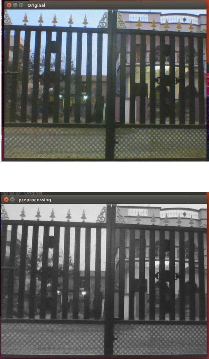
Fig 4.1 Original Image
The Video has been captured using a camera module and Frames of the video are
extracted and the individual frame is considered as an image.

31
Fig 4.2 Preprocessing Image
The image is blurred using Gaussian filter and median blur to remove unwanted
noise from image.
Fig 4.3 Color Segmentation Image

32
Fig 4.4 Edge Detection Image
Morphological operations are used to achieve more accurate edge detection from
the depth image.The key operators for morphological operations are erosion and
dilation. We have used erosion after blurring operations which is followed by two
iterations of dilation.
Fig 4.5 Saved Data Image
The data of pothole saved in the matrix form after the pothole is detected for the
future use.
33
CHAPTER – 5
CONCLUSION AND FUTURE ENHANCEMENT
5.1
CONCLUSION
Various choices for implementing the System have been studied. These
choices were also compared to each other on various criterion. We have specified
the High level design choices of the Subsystems and justified the corresponding
selections. We did experiments on the platform called Firebird. We were also able
to characterize road condition into categories like smooth, moderately uneven and
highly uneven from the results of the experiments.
5.2
FUTURE ENHACEMENT
In future we propose to do more experiments with variety of the scenario.
Our next and immediate step is to use the Accelerometer on real vehicles and
measure their response. Apply different scenarios like potholes on the slopes,
turns and see how the accelerometer readings can characterize such condition.
Along with that in remaining January and February we want to come up with and
formalize the alternate solution for the Localization subsystem.
In next months we perform simulations for given scenarios in
Communication subsystem. And we plan to come up with values for the related
parameters. For example Loss in throughput because of increase in number of
vehicle, Loss in vehicle throughput because of the increase in speed. In the later
months we perform the more experiments regarding the Localization system. If we
are not able to come up with alternate solution; Then we will perform the
experiments regarding integration of the rest of the system with GPS.
34
REFERENCES
[1] R Gass, J Scott, C Diot, “Measurements of In-Motion 802.11 Networking”,
IEEE Workshop on Mobile Computing System and Applications, 2006.
[2] X Zhang, JK Kurose, BN Levine, D Towsley, H Zhang , “Study of a bus-based
disruption-tolerant network: mobility modeling and impact on routing”, 13th
annual ACM international conference, 2007.
[3] “ http://www.its.dot.gov/vii “, RITA | ITS | Vehicle Infrastructure Integration,
JAN 2007.
[4] “ http://dev.emcelettronica.com/datasheet/st/LIS3L06AL “, Datasheet of ST
LIS3L06AL accelerometer, JAN 2008.
[5] “ http://www.gps.gov/ “, Global Positioning System, JAN 2007.
[6] JW Byers, M Lubyt, M Mitzenmachert, “A Digital Fountain Approach to
Reliable Distribution of Bulk Data”, SIGCOMM, 1998.
[7] M Mitzenmacher, “Digital fountains: a survey and look forward”, Information
Theory Workshop, 2004. IEEE, 2004.
[8] “Pothole detection System using WiFi”, Mtech project Report submitted by
Shonil Vijay, JUL 2007.
[9] “FireBird Reference manual”, Embedded and real Time Systems Lab,
Computer science and Engineering Department, IITB
35
APPENDIX
A.
SAMPLE CODE
import cv2
# np is an alias pointing to numpy library
import numpy as np
# capture frames from a camera
cap = cv2.VideoCapture(0)
# loop runs if capturing has been initialized
while(1):
# reads frames from a camera
ret, frame = cap.read()
# converting BGR to HSV
hsv = cv2.cvtColor(frame, cv2.COLOR_BGR2HSV)
gray = cv2.cvtColor(frame, cv2.COLOR_BGR2GRAY)
# define range of red color in HSV
lower_white = np.array([0, 0, 200])
upper_white = np.array([145, 60, 255])
# create a red HSV colour boundary and
# threshold HSV image
mask = cv2.inRange(hsv, lower_white, upper_white)
# Bitwise-AND mask and original image
res = cv2.bitwise_and(frame,frame, mask= mask)
# Display an original image
cv2.imshow('Original',frame)
# finds edges in the input image image and
# marks them in the output map edges
edges = cv2.Canny(frame,100,200)
# Display edges in a frame
#cv2.imshow('input',frame)
cv2.imshow('preprocessing',gray)
cv2.imshow('colour_seg',hsv)
cv2.imshow('Edges',edges)
print mask
36
# Wait for Esc key to stop
k = cv2.waitKey(5) & 0xFF
if k == 27:
break;
# Close the window
cap.release()
# De-allocate any associated memory usage
cv2.destroyAllWindows()
37
B.
SCREENSHOTS
Fig 1 Original Image
Fig 2 Preprocessing Image

38
Fig 3 Color Segmentation Image
Fig 4 Edge Detection Image

39
Fig 5 Saved Data Image

40
C.
PUBLICATION WITH PLAGIARISM REPORT
Detecting Potholes Using Image Processing Techniques and
Real-World Footage
M. B. Sai Ganesh Naik
1*
, V. Nirmalrani
2
1
Sathyabama Institute of Science and Technology, Chennai, Tamilnadu, India
2
Sathyabama Institute of Science and Technology, Chennai, Tamilnadu, India
1*
saiganesh121171@gmail.com,
2
nirmalv[email protected]om
Abstract :-Roads are themain mode for transportation, now a days. As we use roads heavily and
frequently it sometimes leads to potholes. Environmental factors also leads to potholes in several ways.
These potholes are main reason for many accidents. A Scheduled and proper maintenance is required
where we need to monitor each and every road. AS this maintenance of all the roads at a time is not
possible because it is not easy to monitor every single place or just because people ignore to check
which causes formation of potholes that causes unnecessary traffic and many of accidents. To monitor
all the roads this project for pothole detection using image processing techniques implemented. To test
the performance of the proposed system is going to be implemented in a linux environment using Open
CV Library. Techniques of Image processing which detects the potholes on roads and save the data of
pothole for road maintenance department. This helps in keeping manual labour to the minimum
number. Canny Edge Detecting technique and alone with the Contour Detecting Technique are
techniques of Image Processing we use in the proposed system. Hough transformation technique in the
end gives effective output of potholes, very accurately.
Keywords :- Image Processing, Canny Edge, Potholes Detection, Otsus’s method, Gaussian filter.
1.1. Introduction
41
The most frequently mounting problems of the roads are facing is Damaged road conditions. For many
reasons like earth quakes, accidents on roads, wear and tear of top layers of roads make the drivers to drive
on those roads. Unexpected Obstacles on roads may cause number of accidents. Also because of worse road
conditions, the vehicles consumes a lot of fuel unnecessarily. For these are the reasons it is very significant to
get the data of such damaged roads. POTHOLES are the crack-up’s on roads that are formed on the roads for
many reasons where the top road layers will get tattered by heavy traffic. Once after formation ofpothole the
size of hole will keep increasing till we ready that road or repair the pothole, which is main causes for Road
mishap’s. Potholes on roads are particularlyaffects for drivers rushing at high speed. At high speeds a driver
almost inconceivably can notice the potholes on road surface. None the less the drivers may see the potholes
before they cross it, it normally will be too late for a driver to respond to the pothole. A sudden turn or
sudden braking will mostly causes car roll-over. Triggered to the above reasons, we introduced a system that
detects potholes and the proposed system will produce the three dimensional data of potholes and save data
information data and we can retrieve that data and get pothole image. In this paper we use different edge
detection techniques to detect potholes on road. Canny edge detection technique, the most important
algorithm we used here to detect potholes. It detects potholes very accurately and stores the data for future
maintenance of roads. We use a web camera to record the roads and click the images because comparing to
the costly high speed Three Dimensional traverse scanning equipment, web camera is cheap and expensive.
1.2. Related Work
1.2.1. Automatic Pothole Detection
This has crystal rectifier to several accidents inflicting loss of lives and severe injury to vehicles. several
techniques are planned within the past to sight these issues victimization image process ways. however there
has been very little work specifically dispensed for detective work such problems with Indian roads. Potholes
will generate injury like pneumatic alloys injury, jolt and injury of bottom side of vehicles, car or bike
destructions, and big mishap’s. Hence, precisely and hastily detective work potholes should be one amongst
all of the necessary processes of detecting correct methods in ITS services. Many attempts many efforts are
created for progressing the technology which might mechanically sight and acknowledge potholes. during
this project, a hole 2 dimensional (2D) pictures primarily based hole detection technique is employed for
rising the prevailing technique. this method proposes a system Automatic sight the amount of recently
revealed papers addressing crack detection Associate in Nursing classification of asphalt surface affliction
displays an alluring interest during this space. A recent journal, a stratified gift in [1], that cope with
disclosure of roads and inclinations. During this paper, unique groundwork is planned for separating roads
pictures in an exceedingly stratified presence so that may divide the subsequent things. The analysis displays
that the accession during this paper are able to do a glad output on the varied images of road. The lanes
square measure disorganized, that square measures additional advanced more than the organized roads. In [2]
the multi scale accession supported Andre Mark off odd field is planned to section adepts in road concrete
surface pictures. Adepts square measure increased employing one dimensional filter of Gaussian used for
smoothing and so handled by the filter that matches two dimensional to sight them. Complete sixty four road
or lane asphalt layer pictures exhibiting many adepts sorts square measure thought of for experimentation,
manufacturing a qualitative analysis. Characteristic details of image or sort detector accustomed will click
them aren’t given. Another paper [3] evidences the problem of detective work cracks of but three millimeter
dimension once victimization edge detectors. A non-sub sampled contour let rework that has been ratified in
[4] for sight adepts, whereby restricted collection of developmental outputs are conferred. A whole
methodology to mechanically sight and characterize top surface defects are planned at [5], victimization gray
scaled pictures that are clicked with line scanning cameras where lasers lit them throughout road analysis
executed employing an image acquisition system with high speeds. Detection of Adepts uses tentative texture
property activity for every picture. The outputs conferred square measure encouraging, however
developmental analysis doesn’t brace excellence of number of cracks within same picture. In paper [6],. NN
technique is employed. The machine-driven pavement defect detection will solely establish crack kind
defects. To classify defect, a multi-layer perceptron neural network (MLPNN) is employed. NN is employed
to segregate the pictures into four classes: defect-free, crack, joint and bridged. Experimental results square
measure performed on real road pictures that square measure labeled by human operators. There square
measure additional further filters needed for this method. In paper [7], Vision-based approaches square
measure accustomed address functionalities like detection of marking lanes, recognition of traffic signals,
42
detection of pedestrians, etc. this method is feasible to sight the free paved surface before the ego-vehicle
victimization Associate in Nursing on board camera. Novelty technique is employed for each shadowy and
not shadowy regions which give highest performance. Detection of roads formula is hatched by combining
the fuel constant feature area, probability primarily of classifier based. Defect of this method is below
saturation by rising image acquisition system. In paper [8], A NN primarily based approach for the
classification of sections of lane pictures into adepts and traditional pictures. The options square measure
passed for the classification to NN into the pictures including and while not cracks.
1.2.2. Smart Sensing Of Potholes and Obstacles In Automotive Applications Using
Internet Of Things
It is a sensing method which uses light pulses to ascertain the surface of earth. The major drawback in this
method is, it is highly affected by heavy rain, fog, etc. Also does not work well at huge reflections .The
operating cost for this approach is comparatively high. The proposed the 3d laser method to detect potholes
and obstacles. The 3D laser checking is one of the outstandingly flexible and productive advances for
precisely catching extensive arrangements of 3D facilitates. This method uses laser pulses to detect the
irregularities in road surfaces. It is applicable to 2d and 3d surfaces. The disadvantage of this approach is that
it requires post-processing to produce a usable output i.e., the output requires manipulation. And high end
hardware is required where others used the RGB image processing technically ,complex figuring devices that
consolidate programming and equipment to process the pothole pictures are required in this technique. It is
also consumes more time when compared to other methods. Also the accuracy rate is low in this approach.
Moreover it needs prior knowledge of the images i.e., a large quantity of training sets have to be given. Wang
didn’t attainability concentrate to lead the comprehensive review of asphalt conditions by methods for of
stereovision innovation. In this strategy, two advanced cameras are appended to the vehicle, which is utilized
to cover an asphalt surface. The initial step is to dissect 2D pictures from every one of the two cameras to
recognize and order any splits. To recuperate the 3D properties from given sets of 2D pictures on a similar
asphalt surface, the succession of steps, for example, camera alignment, twisting right, coordinating stereo
focuses, 3D recreate, and profile report ought to be performed.It needs complex computation capabilities
when compared to other methods.
1.2.3. Detection, Notification of Potholes, Humps Using Android Application
In this System the process of image pre-processing is done by accomplishing the differences between
Gaussian-Filtering to the Clustering Image segmenting strategies for best and clear fallout’s. The main
aspiration of this gazette was recognizing the principal technique which was enormously gratifying and
actual correlated to traditional techniques. They used different types of image processing techniques and
segmentation methods to detect the pothole where they follow up to take advantage of beheading measures.
The recognition of different scenarios of image processing for detecting pothole was done by correlating
measures of performance with different segmentation methods. Drawback with this system, assassinating and
applying the neural networks which are hybrid classifiers like fuzzy rule base to advance place alone device
to recognize pothole. And proposed a low complexity technique for analyzing and run down of potholes by
the input source fixed inside a running vehicle. The interest for pothole detection is chosen as territory of
picture and the area is seen with maximum resolution. The applicant fields were producedapplying threshold
design. The asset of this journal was accuracy in detection.
1.3. Existing System
In an existing system a detection which starts with noise removal, followed by brightness adjustment and
rendition of video by doing the process ofbinarization. Then, removal of noise is applied to the binarized
image. After noise removal, the process of extracting the framework or outlines for the objects that are
segmented is carried out. Extraction is followed by selection, square zoning for the objects. After all these
processes, desired pothole area information is returned And another system that detects pothole which is
categorised in to 3 subsystems. The encountered potholes are sensed by this first subsystem namely sensing
subsystem, by using accelerometer or by camera which scans the road. Both are mounted on the car. Then
there is another subsystem that is used to transfer the data between WiFi access points to the mobile nodes.
The data about potholes is broadcasted by access point in its areaIn the existing system, the pothole is
detected using the accelerometer sensor in smart phone. This system is not automotive in nature. The

43
complaints if needed to be posted or to be informed to any governmental authority it will be done only with
human intervention. This process may not provide the complete efficiency as many people may ignore the
issue and will not post them. Even if people sends the complaint to an admin many pothole image may be
repeated and thus it may cause a huge confusion. In this case, if prioritization has been done then it would
bean optimized way to collect the frequent places that is being affected by potholes.
1.3.1. Disadvantages Of Existing System
GSM technology has been used which causes delay in message delivery. It is a paid message service. The
severity is less estimated. It is exceptionally costly in nature and it can't be connected to working class level
vehicles.
1.4. Proposed System
In this proposed system Video has been captured using a camera module interfaced with raspberry pi. Frames
of the video are extracted and the individual frame is considered as an image which is further processed. The
image is firstly blurred using aver aging then it goes through Gaussian filet technique and lastly through
median blur for removing unnecessary noise in the image. We modified the process with morphological
operations just for achieving the most approximate detection of edge from the depth image. In general, these
operations are a group of nonlinear operations that are carried out analogously on ordering of pixels without
stirring their numerical values. Erosion, Dilation are morphological key operators.We have used erosion after
blurring operations which is followed by two iterations of dilation. The pothole detection is utilizing canny
edge detection technique. Detection techniques are multi - stage method to detect wide ranges of edges in
images.
1.4.1. Advantages of Proposed System
Easy to Replacement and maintenance.
Fast in identifying the pothole.
Very cost efficient product.
Simple method and Improves efficiency.
1.4.2. System Architecture:

44
Fig 1.4.2.Overview of The Proposed System.
1.5. Implementation
1.5.1. Canny Edge Detection
Canny edge detection technique is a detection algorithm which uses multi stage algorithm undergoes five
stages. It starts with applying Gaussian filter which is used for image smoothing and removal of unnecessary
noise. Then as a second step it finds out the intensity angles of the image form the first step. Then it applies
non-maximum suppression technique to dispose of false edges. Then to detect all possible edges it uses
double threshold method. Finally it detects the proper edges by removing all the false edges which are not
connected with strong edges.
1.5.2. Gaussian Filter
Gaussian filter, used to blur the image and cut down the noise which does unsharp masking that will blur the
edges and cut down contrast.
1.5.3. Otsu’s Method
We use Otsu’s method for reducing the grey level image into a binary one. It assumes that the image or
picture consists of two classes pixels that follows bi-modal histogram. Then it will calculate optimal edge
value where two classes are separated and combined diffusion will at be minimum or equal and inter class
deviation will at maximum.The system then uses contour detection technique. For better accuracy, use binary
images. So we have applied threshold and canny edge detection.While capturing video the hassle of adjusting
speed is eliminated. Hence, the images give a clear view.
1.6. Results
Fig 1.6.1.Preprocessing Image

45
Fig 1.6.2.Color Segmentation
1.7. Conclusion
Fig 1.6.3.Edge Detection
The proposed method describes Image processing techniques for detection method and segmentation of
potholes, accurately.For this process to happen and to achieve the accuracy we need to combine the texture
with gray scale information. These processes to be applied in real world to avoid major accidents. In real
world we have many cc cameras now a days on the roads which are used for traffic purpose and we can use
the same cameras for maintenance of roads and detecting the potholes.
References
[1]. R Gass, J Scott, C Diot, “Measurements of In-Motion 802.11 Networking”, IEEE Workshop on Mobile
Computing System and Applications, 2006
[2]. X Zhang, JK Kurose, BN Levine, D Towsley, H Zhang , “Study of a bus-based disruption-tolerant
network: mobility modeling and impact on routing”, 13th annual ACM international conference, 2007
[3]. “http://www.its.dot.gov/vii”, RITA | ITS | Vehicle Infrastructure Integration, JAN 2007
[4]. “http://dev.emcelettronica.com/datasheet/st/LIS3L06AL”, Datasheet of ST
[5]. LIS3L06AL accelerometer, JAN 2008
[6]. “http://www.gps.gov/”, Global Positioning System, JAN 2007
46
[7]. JW Byers, M Lubyt, M Mitzenmachert, “A Digital Fountain Approach to Reliable Distribution of Bulk
Data”, SIGCOMM, 1998
[8]. M Mitzenmacher, “Digital fountains: a survey and look forward”, Information Theory Workshop, 2004.
IEEE, 2004
[9]. “Pothole detection System using WiFi”, Mtech project Report submitted by Shonil Vijay, JUL 2007
[10]. “FireBird Reference manual”, Embedded and real Time Systems Lab, Computer science and
Engineering Department, IITB

47
ORIGINALITY REPORT
2
%
1%
1%
1%
SIMILARITY INDEX
INTERNET SOURCES
PUBLICATIONS
STUDENT PAPERS
PRIMARY SOURCES
1
www.ijitee.org
Internet Source
2
Submitted to Harare Institute of TEchnology
Student Paper
3
www.it.iitb.ac.in
Internet Source
Valliammal, N., and S. N. Geethalakshmi.
"Hybrid Image Segmentation Algorithm for Leaf
Recognition and Characterization", 2011
International Conference on Process
Automation Control and Computing, 2011.
Publication
1
%
<
1
%
<
1
%
<
1
%
Exclude quotes On
Exclude bibliography On
Exclude matches Off
4
