
House extension
installation guide

Guardian Building System
wall panels
Kingspan Nilvent
®
breathable membrane
Guardian offer a unique opportunity to provide an affordable high-performance
house extension in a complete package from a single source.
2
Guardian Warm Roof System
– fully tested and approved to all
thermal and structural standards
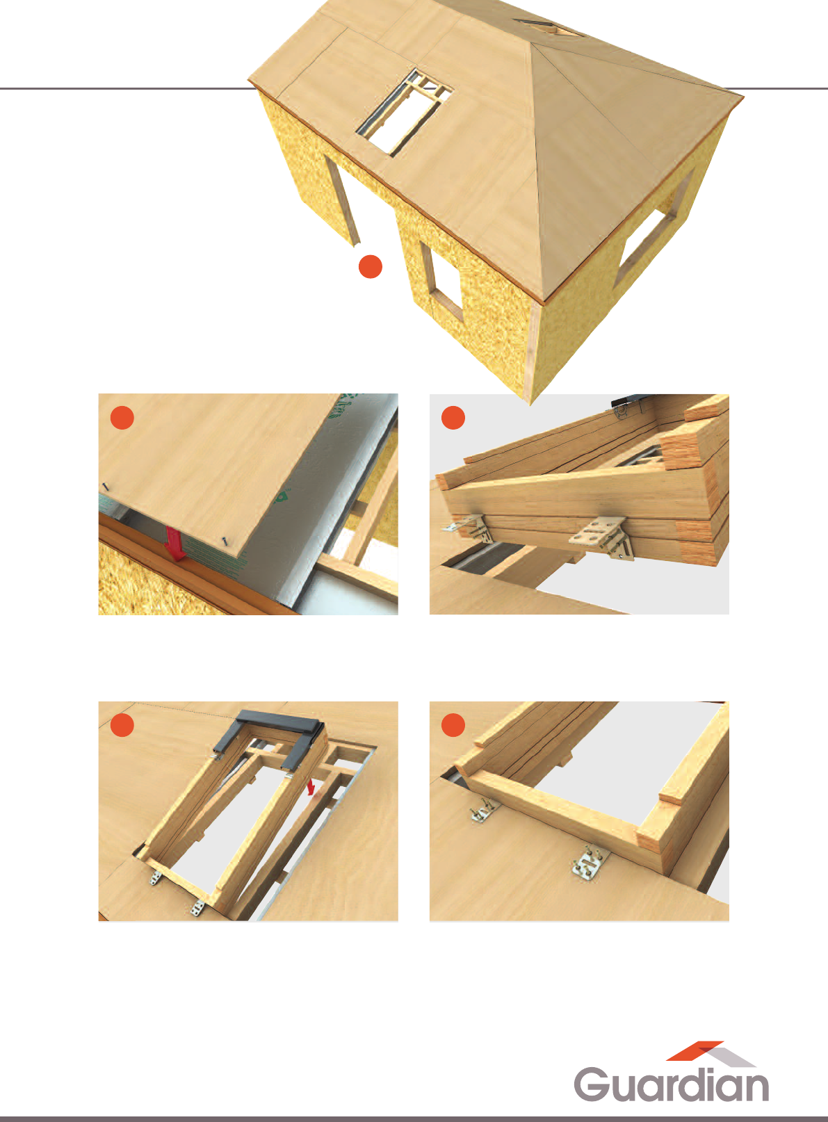
Guardian house extension at a glance

External finish options available
to suit existing structure
OSB jointing
Window / door openings
Sole plate to
foundation
3
Brick slip Brick
Stone
Timber
Render
Other finishes
available on
request.
Erection of first wall
www.guardianroof.co.uk

Foundation assessment
The top level of the slab shall also not vary from the
d
esign by more than ± 5 mm. Slight variations in
foundation dimensions can be dealt with when setting
the soleplate, but variations outside of these tolerances
will make panel erection significantly more difficult. If the
diagonals do not match exactly, some adjustment can be
m
ade when setting the soleplates. If the diagonal
measurements are not given on the foundation or first
floor plan, they can be calculated by using the formula
c = a
2
+ b
2
as shown below.
It is extremely important that you provide an accurate,
l
evel and square platform on which to erect the Guardian
extension.
Ensure the soleplate of the building exactly matches the
d
imensions of the extension, and that all corners are
square.
Foundation width and length should be within 5 mm
of the dimensions called for in the foundation plans.
Check the diagonal as shown in the diagram below. Pairs
of diagonal measurements should be within 5 mm.
Checking Foundation Square
The base or foundation should be swept and cleaned of all material and debris before starting erection of the
extension.
A
C
B
Equal
lengths
c = a
2
+ b
2
4
Wall Installation

Combination soleplate installation
Preparation of Combination Soleplate
T
he combination soleplate (see Figure 1) comprises a
damp proof course (DPC) below a 40 mm x 140 mm
treated timber soleplate below a 50 mm x 110 mm timber
bottomplate. The complete unit is then fixed to the
foundation or substructures.
Caution: Timber soleplates must be treated.
First, connect the soleplate to the bottomplate in
accordance with the fixing method (figure 1), ensuring
that two beads of silicone sealant are applied between
the two elements prior to fixing.
Hint: Use a scrap of 15 mm wood as a gauge when
you position the bottomplates.
Then, apply two beads of silicone sealant to the topside
of the DPC to create a seal between it and the treated
timber soleplate. The DPC should then be fixed to the
underside of the treated timber soleplate, flush to the
inside edge, using two rows of staples at 100 mm centres
(rows should be staggered).
Positioning and Fixing Combination Soleplate
Accurately mark out all internal and external wall
positions using a tape and chalk line. Using a Surveyors
Level or laser, proceed to level the soleplate by taking
levels at 1 m intervals along the lines of the walls in order
to find the highest point. Using the level of the highest
point as a datum, raise the treated timber soleplate at all
other locations using shims to match this level. All points
should be shimmed to within +/– 1 mm. Colour coded
shimming strips are available in various sizes from 2 mm
to 6 mm as detailed in the table below.
Figure 1: Preparation of Combination Soleplate
Position and fix the combination soleplate over the shims
(
DPC facing down) in accordance with the structural
calculations and appropriate Guardian Building System
standard details. Where posts or columns bear directly
onto the slab these should be located using steel shims
only (not plastic).
To seal against air infiltration under the soleplate, point
the gap between the DPC and the base with a non-shrink
cementitious mortar as shown below.
Shim thickness Shim Colour
2 mm Purple
3 mm Green
4 mm Yellow
5 mm Blue
6 mm Black
Anchor bolt and washer as per details
given in structural calculations. Bolts to be
s
upplied by contractor
3.1 mm x 90 mm galvanised
ring–shank nails
2
beads of silicone sealant
5
0 mm x 110 mm bottomplate
4
0 mm x 140 mm soleplate
Shim
D
amp proof
membrane (DPM)
Damp proof course (DPC) Foundation
5
www.guardianroof.co.uk
1

Figure 2: Installation of Combination Soleplate
Figure 3: Application of Mortar Under Combination Soleplate
Silicone
s
ealant
3.1 mm x
9
0 mm galvanised
ring–shank nails
Anchor bolt and washer
a
s per details given in
structural calculations.
Bolts to be supplied by
c
ontractor.
5
0 mm x 110 mm
bottomplate
4
0 mm x 140 mm
soleplate
DPMDPCFoundation
Shim
Silicone sealant
3.1 mm x 90 mm
galvanised ring–
shank nails
Anchor bolt and washer
as per details given in
structural calculations.
Bolts to be supplied by
contractor
Application of mortar
under combination
soleplate and DPC
50 mm x 110 mm
bottomplate
40 mm x 140 mm
soleplate
DPM
DPC
Foundation
Shim
General
I
t is assumed that the Guardian Building System
registered contractor has made sufficient provision for all
temporary works necessary to assemble the project
safely and that they have prepared method statements
to address difficult stages of work as appropriate. It is
similarly assumed that scaffolding and safe working
platforms will be constructed as the project proceeds
to ensure a safe working environment at all times.
Handling Panels
Guardian Building System wall panels should preferably
be lifted and manoeuvred in accordance with the
contractors method statement, preferably using
appropriate mechanical lifting equipment.
Sorting of Wall Components
The first wall should be started at the external corner
furthest away from the main stack of Guardian Building
System wall panels. The first wall panel to be erected
should be the overlapping corner panel. Identify the
required components for the first wall and place them
near to the wall being erected.
Preparation of The First Panel
All routs should be brushed clean of any debris and
checked for proper forming and depth.
Wall assembly – panel by panel
6
Wall Installation
2a
2b

Erection of The First Wall Panel
Hint: Using site plans as a guide, mark out wall panel
j
oints on the combination soleplate before erecting
the first wall panel. If wall panels joints are not in line
with the markings on the combination soleplate,
corrective action should be taken immediately.
Apply a bead of expanding urethane sealant onto the
bottomplate to ensure that an airtight joint is achieved.
Manoeuvre the Guardian wall panel into position. Push it
right down so that it is in full contact with the top face of
the soleplate. The end timber within the wall panel must
be perfectly flush with the outer edges of the corner.
HINT: Do not nail any Guardian Building System wall
panels into the bottomplate until the roof is on the
house, this will allow the walls to settle onto the
soleplate giving the panel a more even load
distribution.
Check that the wall panel is both level and vertical
prior to installing a diagonal brace that will temporarily
secure the wall panel in its correct position. This can
be done using 50 mm x 100 mm timbers or proprietary
wall braces.
Figure 4: Combination Soleplates Ready to Receive Wall Panel
3.1 mm x 90 mm
galvanised ring–
shank nails
50 mm x 110 mm
bottomplate
40 mm x 140 mm
soleplate
DPCExpanding urethane sealant Foundation
7
Existing wall to extension connectivity
Figure 5: Consideration on how level the wall is as levelling would
be required and the measures to be taken to level the edge timber
ready for the Guardian wall panel. Consideration on installing a
soleplate timber up the wall to help in these very uneven situations.
Existing wall should be pre-levelled out in an appropriate way
using shims/levelling mortar/grout fit for purpose. Secure a
vertical dpc (placed on the back of a vertical treated plate) to
the existing wall. Fix Guardian side plate to wall using fixings
(fixings would be dependant on substraight and would need to
be confirmed with fixing manufacturer).
Figure 7: Silicone seal both sides of the Guardian wall panel to
wall junction.
Figure 6: Install Guardian wall panel starting at the existing wall.
www.guardianroof.co.uk
2c

Figure 8: Erection of First Wall Panel
Figure 9: Fixing First Wall Panel
2
.8 mm x 63 mm
galvanised ring–
shank nails
50 mm x 110 mm
b
ottomplate
40 mm x 140 mm
o
n soleplate
Expanding urethane
s
ealant
F
oundation
50 mm x 110 mm
end timber
2 beads of
s
ilicone sealant
2.8 mm x 63 mm
galvanised ring–
shank nails
Silicone sealant
15 mm x 100 mm OSB3 spline
50 mm x 110 mm end timber
Expanding
urethane sealant
Foundation
DPC
Erecting Subsequent Wall Panels Along the First Wall
Prepare subsequent Guardian Building System wall
panels by fixing OSB3 splines. Apply expanding urethane
sealant onto the bottomplate and into the central vertical
routed channel(s) of the previously erected panel to
ensure an airtight seal is achieved.
Manoeuvre the wall panel into position so that the
timber post or OSB3 spline is ready to engage the
previously erected wall panel as illustrated in Figure 6
below. Firmly push the wall panel into place ensuring
that all edges are tightly abutted. Where joints need
tightening to ensure edges are tightly abutted use
ratchet straps.
8
Figure 10: Wall Panel Joints > 300 mm from Joints in Bottomplates
Figure 11: Wall Panel Joints > 300 mm from Joints in Bottomplates
Manoeuvering Guardian
wall panel into position
OSB3 splines
2
.8 mm x 63 mm
galvanised ring–shank
nails
Silicone sealant
40 mm x 140 mm soleplate
Expanding
u
rethane sealant
50 mm x 110 mm
bottomplate
F
oundation
50 mm x 110 mm
bottomplate
Guardian wall panel
f
ixed into position
2
.8 mm x 63 mm galvanised
ring–shank nails
Expanding urethane
sealant
Foundation
40 x 140 mm
soleplate
Caution: Ensure butt joints in the bottomplate are a
minimum of 300 mm away from the Guardian
Building System wall panel joint.
Wall Installation
2d
2e 2g
2f

Figure 12: Erection of Subsequent Wall Panels
40 mm x 140 mm
on soleplate
E
xpanding
urethane sealant
Foundation
M
anoeuvre subsequent
Guardian wall panel
into position
Guardian wall panels
fixed into position
2
.8 mm x 63 mm galvanised
ring–shank nails
1
5 mm x 100 mm
OSB3 spline
50 mm x 110 mm
bottomplate
Figures 13 and 14 below illustrate the two standard wall
p
anel jointing methods
.
Figure 14: Fixed OSB3 Spline Joint
Figure 13: OSB3 Spline Joint
15 mm x 100 mm
0SB3 splines
Guardian wall panel
Expanding urethane sealant
Expanding urethane sealant
2.8 mm x 63 mm galvanised
r
ing–shank nails
2.8 mm x 63 mm galvanised
r
ing–shank nails
G
uardianwall panel
9
With the wall panel in position, fix the remaining
fasteners along the joints.
The final wall panel within the wall should be fitted with
an end timber, which should be fixed to allow correct
corner assembly.
Again, the end timber within the wall panel must be
perfectly flush with the outer edges of the corner.
HINT: A temporary raking wall brace should always be
placed within 200 mm of junctions between interior
wall and exterior walls to ensure that this load
bearing connection can be properly formed.
www.guardianroof.co.uk
2h

Erecting Subsequent Walls
T
he corner joint should first be sealed with two beads of
silicone sealant and then fasteners should be fixed
through the corners into the end timbers.
T
he rest of the walls should be erected in a similar
manner. When all exterior and interior walls have been
erected and headplates have been installed a horizontal
line should be pulled between pairs of building corners to
finally check that wall panels are correctly located.
Additional racking braces should be used (or adjusted) to
make any necessary wall panel realignment.
Where the Guardian Building System wall panels
are used as internal walls, they need to be plumbed and
levelled with the top of the external walls, braced as
before and fixed.
As with external walls, use adjustable wall braces
where necessary to ensure internal walls are in their
correct position.
Hint: Ensure that sufficient wall braces are used to
stabilise the wall construction during the erection of
the final storey and that these remain in place until
the roof has been completed.
Figure 15: Creation of Corner Joint
Figure 16: Fixing of Corner Joint
6.0 mm x 210 mm
nail
F
ormation of
corner joint
5
0 mm x 110 mm
end timbers
Silicone sealant
Guardian wall panel
2
.8 mm x 63 mm
galvanised
ring–shank nails
50 mm x 110 mm
end timbers
2 beads of silicone sealant
Manoeuvering
Guardian wall
p
anel to form corner
10
Wall Installation

S
tandard Door and Window Openings
Guardian Building System wall panels will arrive (unless
specified otherwise) from the factory pre-cut and routed
for window and door openings. The routed grooves will
(unless specified otherwise) be 50 mm deep so that the
50 mm x 110 mm edge timbers can be fully inset around
the whole window or door perimeter as illustrated. These
timbers need installing as soon as the wall panels have
been erected to prevent excessive amounts of water
standing in the rout.
Edge timbers should be installed as previously
described, above both when the opening is enclosed
within one Guardian Building System wall panel and also
when it extends into any adjoining wall panels. With all
openings for windows and doors, the edge timbers
should be cut and installed into the routed channels to
match the configuration illustrated. This helps distribute
the load carried by the edge timber that forms the timber
headplate.
Figure 17: Opening for Window
Figure 18: Opening for Window – Cross Section
E
xpanding urethane
sealant
2
.8 mm x 63 mm
galvanised
ring–shank nails
Foundation
40 mm x 140 mm
soleplate
50 mm x 110 mm
bottomplate
5
0 mm x 110 mm
edge timber
100 mm x 110 mm
timber posts
G
uardian lintel
Guardian
wall panel
Guardian
wall panel
50 mm x 110 mm
edge timber
100 mm x 110 mm
timber posts
Guardian lintel
Foundation
40 mm x 140 mm
soleplate
50 mm x 110 mm
bottomplate
11
www.guardianroof.co.uk
3a
3b

Large Openings
V
ery wide windows and large doors often span more than
a full Guardian Building System wall panel. In this case,
the plans may call for a more substantial beam or lintel
that is inset into the panels.
Figure 19: Beams or Lintels Above Window and Door Openings
Figure 20: Beams Or Lintels Above Window and Door Openings
– Cross Section
Figure 21: Beams or Lintels Above Window and Door Openings
Figure 22: Beams or Lintels Above Window and Door Openings
– Cross Section
Expanding
urethane
D
PC
2
.8 mm x 63 mm
galvanised
ring–shank nails
Foundation
4
0 mm x 140 mm
soleplate
5
0 mm x
110 mm
bottomplate
50 mm x 110 mm
e
dge timber
1
00 mm x 110 mm
timber posts
Strip of OSB3 to
c
over timber
G
uardian lintel
G
uardian
wall panel
Expanding
urethane
DPC
Foundation
40 mm x 140 mm
soleplate
50 mm x
110 mm
bottomplate
100 mm x 110 mm
timber posts
Guardian lintel
Guardian
wall panel
Expanding
u
rethane
D
PC
2
.8 mm x 63 mm
galvanised
ring–shank nails
Foundation
4
0 mm x 140 mm
soleplate
5
0 mm x
110 mm
bottomplate
5
0 mm x 110 mm
edge timber
1
00 mm x 110 mm
timber posts
Strip of OSB3 to
c
over timber
G
uardian lintel
G
uardian
wall panel
Expanding
urethane
DPC
Foundation
40 mm x 140 mm
soleplate
50 mm x
110 mm
bottomplate
100 mm x 110 mm
timber posts
Guardian lintel
Guardian
wall panel
12
Wall Installation
4a
4b
4c
4d

Setting out Wall Panels Prior to Assembly
O
rganise the Guardian Building System wall panels into
their designated positions on a level surface, (e.g. if the
wall panel is resting on a combination soleplate it will
not be level and therefore cannot be pulled together as
an entire wall section) external face up, to match the
detailed construction drawings provided with each
project. At this stage leave a 25 mm gap between wall
panels to aid assembly.
Hint: Prior to undertaking this method of Guardian
Building System wall panel erection it is extremely
important to plan the sequence of panel assembly so
that site or building constraints can be
accommodated.
Figure 23: Ensure Wall Panels Are Laid Flat
Figure 25: Bring Wall Panels Together Using Ratchet Straps
1
00 mm x 110 mm
timber post
Silicone sealant
F
actory routed channels
for OSB3 splines
F
actory routed channel to accommodate
50 mm x 110 mm bottomplate
50 mm x 110 mm
bottomplate
40 mm x 140 mm soleplate
Expanding urethane sealant
Foundation
DPM
DPC
Guardian
wall panel
100 mm x 110 mm
t
imber post
Silicone sealant
Factory routed channels
f
or OSB3 splines
Factory routed channel to accommodate
5
0 mm x 110 mm bottomplate
50 mm x 110 mm
bottomplate
40 mm x 140 mm soleplate
E
xpanding urethane sealant
F
oundation
D
PM
DPC
Guardian
w
all panel
Figure 24: Install OSB3 Splines
100 mm x 110 mm
t
imber post
Silicone sealant
Factory routed channels
f
or OSB3 splines
Factory routed channel to accommodate
5
0 mm x 110 mm bottomplate
50 mm x 110 mm
bottomplate
40 mm x 140 mm soleplate
Expanding urethane sealant
Foundation
DPM
DPC
Guardian
wall panel
Wall assembly – entire wall sections
13
www.guardianroof.co.uk
5a
5b
5c

Joining Panels Using OSB3 Splines
S
lide the OSB3 splines into the Guardian Building
System wall panel joints as illustrated.
Pull the wall panels together using a ratchet strap having
m
ade sure the OSB3 splines are not intruding into the
50 mm x 110 mm routed channel at the top and bottom of
the wall panels.
Before the insulated spline is fitted, expanding urethane
sealant should be injected into each rebate to create an
airtight seal.
Figure 26: Fixed OSB3 Spline Joint
Closing Joints in Wall Sections
When using ratchet straps to close joints, it is imperative
that the Guardian Building System wall panel edges are
adequately reinforced or protected to prevent damage to
the OSB3 facings, as illustrated in figure 25.
Caution: Do not attempt to lift large Guardian Building
System wall sections manually – use correct lifting
procedures.
14
Guardian wall panel
E
xpanding urethane sealant
2.8 mm x 63 mm galvanised
ring–shank nails
Assembly, Nailing and Raising of Further Wall Sections
F
urther Guardian Building System wall sections should
be constructed and erected in the same manner.
Hint: Ensure Guardian Building System wall sections
are erected in the correct sequence so as to optimise
t
he use of working space and resource.
Particular care should be exercised when assembling the
wall sections that include either window or door openings.
In certain situations some additional temporary bracing
members may be necessary, nailed across breaks in
Guardian Building System wall panel edges.
.
Hint: Ensure that sufficient wall braces are used to
stabilise the wall construction during the erection of
the final storey and that these remain in place until
the roof has been completed.
Wall Installation

Figure 28: Formation of Corner Joint in Wall
Figure 27: Bracing Wall Sections
Fixing Wall Panels Together At Corners
F
ix through the corners into the end timbers through
pre-drilled 4 mm dia. holes, illustrated below. It is
extremely important to apply two continuous beads of
silicone sealant along these types of joint.
Figure 29: Fixing Wall Panels Together at Corners
50 mm x 110 mm
h
eadplate
Foundation
4
0 mm x
140 mm
soleplate
Adjustable steel
w
all brace
Expanding
urethane sealant
5
0 mm x
110 mm
end timber
Temporary
wall brace
o
n outside
edge
DPC
Guardian
w
all section
50 mm
x
110 mm
bottomplate
Raising The Wall
A
pply a bead of expanding urethane sealant onto the
bottomplate. Tilt the Guardian Building System wall
section using either a crane or another appropriate piece
of mechanical lifting equipment and following the
contractor’s method statement for safe working. Attach
temporary wall braces as required. To ensure the wall
section is plumb and remains so, brace wall ends on the
outside edge. Attaching the wall braces to the outside
edge allows room on the floor surface for assembly of
further wall sections.
6.0 mm x 210 mm
nail
Formation of
corner joint
50 mm x 110 mm
end timbers
Silicone sealant
Guardian wall panel
2.8 mm x 63 mm
galvanised
r
ing–shank nails
50 mm x 110 mm
end timbers
2 beads of silicone sealant
Manoeuvering
Guardian wall
p
anel to form corner
15
www.guardianroof.co.uk
5d

16
Figure 30: Install Mitred Headplates – cut angle to suit roof pitch
Installing Headplates
H
eadplates tie the Guardian Building System wall panels
together and provide a continuous solid surface to
support the first floor construction. Headplate joints
should be staggered so that they offset wall panel joints
by a minimum of 300 mm. All OSB3 splines, timber posts
and end timbers should not intrude into the routed
channel that will accommodate the headplate.
Expanding urethane sealant should be applied into the
routed channel. The headplate should then be located
within this channel and fixed.
50 mm x 110 mm
end timbers
50 mm x 110 mm
headplate
2
.8 mm x 63 mm galvanised
ring–shank nails
Step OSB board
E
xpanding
urethane sealant
Guardian
w
all panel
Hint: Cut-out section of OSB board to allow
Headplate to fit flush.
Wall Installation
5e

17
www.guardianroof.co.uk

Guardian High-Performance
Warm Roof System
Roof Installation
18

T
imber battens
7
2mm high performance
insulated plasterboard
C
hoice of tile finishes
M
embrane
Rafter
4
0mm high performance insulation
Guardian warm roof construction
E
xterior grade plywood
2
5mm high performance
insulation (timber batten
cut back for clarity)
The following guide has been created to assist in the
fabrication and installation of the Guardian Roof. Please
note that each roof is individual and will be fabricated to
suit various shapes and sizes.
Your fabricator will be available to provide installation
technical support. Your fabricator will include a roof
layout plan and an installation guide with each roof.
Roof Layout Plan
Please refer to the roof layout plan prior to commencing
installation. It is very important that the roof fits the
windows layouts and that all the windows are fully
reinforced. All components are numbered to match the
roof layout plan for ease of installation.
Tools required
l
Cordless drill,
l
Angle grinder,
l
Silicone gun,
l
Tape measure,
l
Hand saw,
l
10mm spanner and 10mm nut spanner,
l
10mm ratchet,
l
snips,
l
staple gun,
l
screwdriver,
l
foam gun and expanding foam.
Step 1:
Installation of roof rafter brackets
www.guardianroof.co.uk
19

20
Step 2: Box gutter
Step 3: Ringbeam
Fix box gutter to wall and seal using suitable sealant.
P
lace ringbeam on the side lip of the box gutter and fix in
place by screwing up through the lip with a 25mm
window screw.
I
t is recommended to run a strip of sealant along the box
gutter channel prior to clipping on the ringbeam.
Please fit insulating foam to underside of box gutter.
Ensure not to puncture the box gutter itself.
For the best internal finish use insulated plasterboard
under box gutter using timber battens.
60mm x 70mm square edged timber is supplied and fit to
the underside of the ringbeam. The inside of the timber
add on should be fit flush with the inside of the window
frame. Bed timber add on onto window frame with
silicone and fix from underneath.
Cleats to be inserted internally into the ringbeam and
fixed using 25mm stainless steel window screws.
Ringbeam and packer should be installed flush with
inside of window frame. Use 100mm stainless steel
window screws at 600mm centres.
2a
3
Roof Installation

21
Step 4: Assemble rafters
Gable rafters to be bolted to house wall and secured at
3
00mm centres using suitable fixings determined by the
wall construction.
Ensure Stainless Steel Cleats provided are used when
f
ixing to the house wall at the top and bottom of wall rafter.
Stainless steel cleats must also be used at gable front end.
Victorian conservatory option
4a
4b
Fix rafter to ringbeam using pre-installed cleats and bolts
provided (loosely tighten at this stage).
Edwardian stainless
steel cleat
Victorian stainless
steel cleat
Edwardian conservatory
www.guardianroof.co.uk

22
Use location pin provided to temporarily
fix arm to spider.
Temporary fix remaining rafters including any
pre-engineered window framing (if required).
4d
4c
Step 4: Assemble rafters
Roof Installation

23
Ensure all roof sections are aligned to the
p
re-engineered positions and tighten into place.
For edwardian/victorian hip cleats tighten bolts on
rafters first before tightening to ringbeam.
Tighten pre-installed grub screws using allen key.
Please ensure grub screws are not overtightened.
4e
4f
Edwardian
aluminium cleat
Victorian
aluminium cleat
www.guardianroof.co.uk

24
Step 5: Timber battens
Fit 25mm timber battens at maximum 400mm centres to
underneath of rafters.
Fixings are to be 5.5mm x 50mm light steel, 3mm-12mm
wing tipped or a Timco 5.5mm x 50mm self drilling screw.
5a
Batten out entire roof structure. Batten over window
opening and cut back to suit.
5b
Step 6: Rafter insulation
From outside insert 40mm insulation board between
rafters.
6a
Seal all gaps with expanding foam.
6b
Any exposed aluminium surfaces or
spider arms visible on the inside
need to be competely covered using
expanding foam.
Roof Installation
25
Install roof window frame into pre-formed opening
within rafters.
7d
Fix frame to timber ply through brackets using screws
supplied within roof window pack.
7e
Timber out roof as per schedule. Ply sheets to be fixed
at 200mm centres using 2.8mm x 38mm Timco self
drilling screw.
7b
Fix brackets to the V notch on roof window frame prior
installation.
7c
7a
Fix timber sheets to rafters.
Step 7:
Exterior plywood
& window frame
www.guardianroof.co.uk

26
Step 8: Membrane & roof tile
Cover with vapour permeable underlay with a vapour
resistance of less than 0.25MNs/gram as required by
BS5250: 2002. Overlap all joints of underlay by 150mm
and staple down to timber sheets. Over run ringbeams
by 100mm and up outer wall by 50mm.
Take underlay up window frame and staple to topside.
Fix watercourse to outer wall. Starting bottom right
corner of the roof with a full roof tile, fix to lip of
ringbeam and into the corner of the watercourse
(allow 4 x 16mm screw fixings per tile).
Roofing membrane must be laid from the bottom up with
the overlap always to the outside as you come down the
roof. This also should be done at hip points.
8b
All tiling is from right to left. Complete one row at a time.
For the second course always start with half a tile.
8c
7a
Roof Installation

27
Dependant on height of roof window 1-3 tiles should be
f
itted below window before bottom flashing is installed.
8d
Contact roof manufacturer for correct installation of roof
window and flashings.
Roof window flashing to be installed to roof window pack
instructions.
8e
Roof window flashings should be
sealed to the breather membrane.
It is
also advisable to run a line of sealant
on top of the flashing and under the
tiles on the sides and the top to
prevent blowback.
www.guardianroof.co.uk

28
Step 9: Standard ridge & end cap
Dress over hip, cut and bend to
shape at intersections
Optional small ridge
Optional end capping
Apply foam tape to underneath the 25mm treated timber
batten. Using the profile ridge and hip for position fit
timber battens and screw into place.
9a
Follow instructions 8a and 8b for end capping. Fix rafter
cap over delta ridge profile at verge.
In cases of stretched Victorians and off angles on ridges,
a smaller ridge is available to allow for angle adjustment.
Paint cut edges with touch-up kit.
9c
Position delta ridge over batten and fix side on.
Use touch up kit provided to hide screw heads.
9b
Roof Installation

29
Step 10: Internal insulation
Step 11: Gutter adaptor
Fit box gutter adaptor into the box gutter and seal using
suitable wet sealant. Seal between ringbeam/extension
and window line with appropriate sealer. Also seal
against house wall.
25mm PIR Insulation to be used under Box Gutter for
insulating value and to avoid the risk of condensation.
Install 25mm foiled insulation between battens and apply
expanding foam to the spider assembly.
75mm insulated foil tape should be run over every batten
so no timber will be visible from the inside.
Please ensure electrical wiring is in place before 25mm
PIR is positioned.
10a
11a
Step 12: Gutter
Twist fit gutter brackets to ringbeam prior to installing
gutter and downpipe.
12a
Tape all joints and seal against window frame, cut
and mitre 72mm insulated foil backed plasterboard, fix
into position.
Fit colour matched cloaking trim to cover inside of timber
add on prior to fitting plasterboard.
All insulation supplied must have a foiled back covering.
10b
www.guardianroof.co.uk

30
Step 13: Valley gutter
Place valley tray on top of breather membrane within the
v
alley itself.
Fix flaps either side directly into membrane and ply.
Tile into valley cutting at angle of roof.
Seal where necessary.
13a
Optional mansard ceiling
Use appropriate low voltage down lighters with cowl.
Guardian Warm Roof suggests the use of Plug and Play
down lighters used with a low voltage LED bulb.
Roof Installation

31
Notes:
www.guardianroof.co.uk

Guardian Roofs (Celuplast Ltd.)
FREE Phone: 0800 0665832 Email: info@guardianroof.co.uk
www.guardianroof.co.uk
